Thanks, Mike! It's also a fun jobOriginally Posted by Mike Heidrick


 [OP]
Contributor
[OP]
Contributor
Thanks, Mike! It's also a fun job
David
CurlyWoodShop on Etsy, David Falkner on YouTube, difalkner on Instagram
[OP]
Contributor
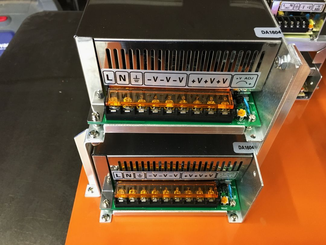
Here's a topic that is likely easy to answer but I suspect there are folks on both sides of this fence: I have two 48V power supplies, 10.4 amp, and we are using four 5.5 amp NEMA 34 stepper motors. I thought it would be a good idea for load balancing to put Z and one Y on one power supply and X and the other Y on the other power supply. My thinking is that if movement is only in the Y direction then the load will be split between the two power supplies rather than all coming from one. Obviously if movement is circular or off the straight line Y axis then at least 3 motors will be engaged at the same time, sometimes all four.
So is that a regular, accepted thing or should both Y steppers be powered by the same PSU?
Thanks in advance!
David
David
CurlyWoodShop on Etsy, David Falkner on YouTube, difalkner on Instagram
Member
Your Y axis stepper drivers and the power supplies do not care what they are hooked too. Only reason to I would keep them together is if you lost one power supply then I would want both axis to not be powered.
Glad its my shop I am responsible for - I only have to make me happy.
Contributor
Definitely don't have much experience in the router side of things, but if you are driving two axis motors for one axis, wouldn't you want both of them on the same drives and power supply? For example, if one side fails and the other is still driving, wouldn't that try to tear the machine apart? If I have an axis failure, I would prefer both motors driving that axis shut down together.... at least that's the way my mind thinks about it.
Brian Lamb
Lamb Tool Works, Custom tools for woodworkers
Equipment: Felder KF700 and AD741, Milltronics CNC Mill, Universal Laser X-600
[OP]
Contributor
Thanks, Mike. That is a consideration, certainly. It would definitely not work very efficiently!
Thanks, Brian. Each motor has its own driver, so there are 4 motors and 4 drivers (soon to be 5 motors and 5 drivers).
_____________________________________
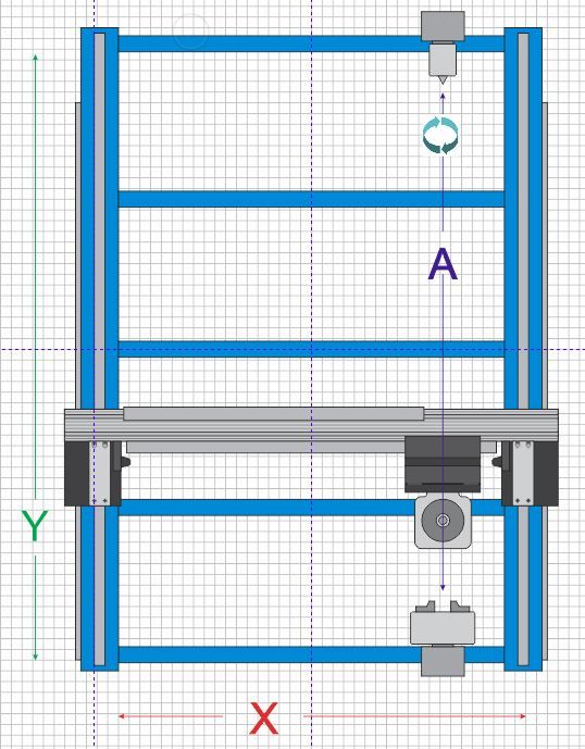
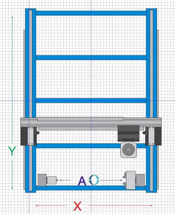
Here's my thought process (scary, I realize...) - My initial design has the A axis primarily on the front of the machine parallel to the X axis for short stock, say 15"-18", but what I've designed will also mount 90° from that and be parallel to the Y axis for longer stock to take advantage of the 4' length of the machine frame.
However, most of the A axis motion will be in small increments or indexing as the X or Y moves along the length of the stock. While it may be necessary on occasion to turn the A axis in continuous motion, like a lathe, I just don't see that being the norm. And if that becomes necessary I would think it to be low speed and low load so it shouldn't even be pulling the full current draw for the A axis stepper motor. For that reason I thought splitting the load for the Y steppers would be good.
I could simplify all this by just placing A along the Y axis for the maximum length stock and just forget about having two configurations for A...
Another thought is I can simply move the two terminals for powering the A stepper driver, as needed, from one power supply to the next in about two minutes. At this time I don't know how often I'll use the A axis so it isn't yet an issue but I have one soon to be frequent customer asking if I'll be able to do any routing on curved or round stock and if I'm able to do that then he's going to want 12-15 items in Walnut every month. If what he wants is short enough to use the A configuration along the X axis then he's going to keep me busy enough to just leave it there and manage the power supplies as needed. Decisions, decisions...
David
CurlyWoodShop on Etsy, David Falkner on YouTube, difalkner on Instagram
Member
When cutting you will not be maxing any of these stepper drivers at all, the speed need wont be there. Even if one was fat it would be highly unlikely you will be concurently maxing the amperages on A and X anyway so it wont really matter. Hook them up and get cutting.
If you want options put a two way selectable switch on and flop to each power supply config as needed or better yet just give A its own power supply and be done.
Glad its my shop I am responsible for - I only have to make me happy.
Member
Perhaps look at redundancy in your power supplies? For example, add a 3rd power supply and wire all of them to a DC buss. The buss feeds all of the axes, etc.. If one fails, the other two can carry the entire system.
Assuming the P/S's have a status relay, you can do 1 of 2 things:
1) Wire an alarm/beacon to the status relays (in parallel) to alert you to P/S failure. You can then take manual steps to mitigate the loss; or,
2) Wire all of the relays in series, then feed signal to your controller. Program the controller so that if you lose a P/S, it could automatically terminate your process.
 Member
David...
The simplest, and possibly the best, option would be to connect the 2 power supply DC out terminals together. This would balance the load and allow any or all drives to access the available power.
Gary Campbell
CNC Replacement & Upgrade Controllers
Custom 9012 Centroid ATC
[OP]
Contributor
That was my thinking on the use of the rotary axis, Mike. This won't be trying to get maximum cut depth and speed, high rapids, etc. I have extra opto-isolated relays available on the little 4-channel board just above the ESS so I could do this electronically pretty easily.
Good ideas, Malcolm - thanks!
I like that, Gary. I've read that some power supplies can't/shouldn't be connected in parallel; I wonder if these are ok being hooked that way...?
David
CurlyWoodShop on Etsy, David Falkner on YouTube, difalkner on Instagram
Member
your project is looking really nice. What will you do for a top?
[OP]
Contributor
Thanks, Ed!
I'll start with two layers of 3/4" MDF and learn on that. I may add T-tracks at some point or recessed threaded inserts but may not do that right away. What do you recommend, Ed?
David
CurlyWoodShop on Etsy, David Falkner on YouTube, difalkner on Instagram
 Member
Paralleling power supplies can be different than paralleling batteries, because batteries don't have voltage regulation circuits and have more internal resistance to absorb the differences in their outputs.... I've read that some power supplies can't/shouldn't be connected in parallel ...
The lower voltage (slightly) power supply's regulation circuit may be causing the other's output to go up to compensate and vice-versa, but that depends on the supply's output circuit. You won't know unless you can isolate one and measure its output current.
Another situation to consider is both supplys powering up at the same time. One may be at zero volts while the other one is at its regulated voltage. The one that isn't on yet will become the load for the one that is fully on (and everything in between.) This will activate protection circuits in the supply's output section.
You could/should contact the manufacturer to get their advice, or you could roll-the-dice and try it!
At any rate, I've paralleled power supplies before (and in the old days of simpler designs) by adding a low-ohm high-watt resistor in the outputs of each supply then connecting the resistors together. This way the resistor loads will absorb any differences in the supply's output. This resistor is called a "ballast resistor." Sometime this resistor was actually a diode.
It isn't a simple problem and there isn't a simple solution, but some power supply manufacturers design this capability into their supplies. Some supplies can have this capability by simply using a "remote sense" connection at the point where the supplies are paralleled. This gets a bit more technical to explain and probably better to look it up elsewhere.
PS. High output car stereo amp nuts used to have to do this to get double the power out so they could get deaf faster.
― Paul
These words are my opinion, WYLION. Any resemblance to truth or fiction is accidental at best.
"Truth lies dormant in our future history." ― Paul Lawrence LXXI
[OP]
Contributor
Thanks, Paul! That's some good info, I knew some of that but some is new to me. I think I'll pass on doing the parallel connection and just see for a while how everything works.
I like your PS!
David
David
CurlyWoodShop on Etsy, David Falkner on YouTube, difalkner on Instagram
Member
Paul is correct that some low end power supplies won't play nice in parallel.
David, I didn't pick up on the voltage or wattage of your P/S's, but if you do decide to pursue parallel connections here is a source for 'redundancy module'. I have no relationship with Phoenix Contact - other than frequent user of full spectrum of their panel-build products (power supplies and redundancy modules included). They make good stuff.
[OP]
Contributor
Thanks, Malcom - that's good info. The PSU's for the steppers are 500 watt, 48V, 10.4 amp each and they're from Stepper Online.
Last edited by David Falkner; 08-30-2016 at 12:02 PM. Reason: Corrected Malcom's name... ;)
David
CurlyWoodShop on Etsy, David Falkner on YouTube, difalkner on Instagram
 Posting Permissions

 Reply With Quote
")
