Jim, I can imagine the "what" and even the "why", but struggle to understand the reason it was considered necessary.
Regards from Perth
Derek


 [OP]
Contributor
[OP]
Contributor
Jim, I can imagine the "what" and even the "why", but struggle to understand the reason it was considered necessary.
Regards from Perth
Derek

 Contributor
It could have been decorative with a wider contrasting band across the tenon. Maybe even a small wedge in the wedge to punch it up a bit.
It could have also allowed for more taper in the mortise.
Worst of all would be, "that's how my teacher always told me to do it."
jtk
"A pessimist sees the difficulty in every opportunity; an optimist sees the opportunity in every difficulty."
- Sir Winston Churchill (1874-1965)
[OP]
Contributor
Beginning the arms and back
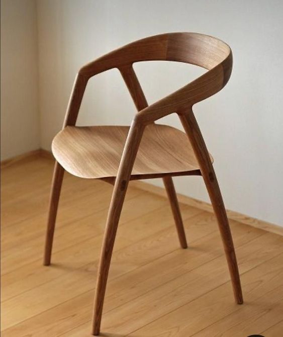
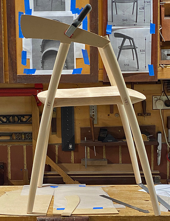
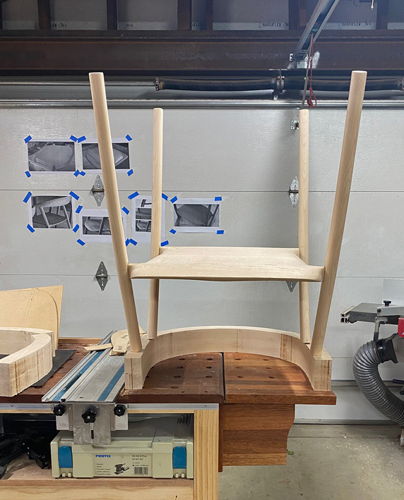
The legs and seats are done and it is time to move to the arms and backs. Once again, the chair to provide a context of where we are headed ...
I was fortunate to find a few photos on the Web showing the development of the arms/back, which provided some insight into how to construct this ...
The construction sequence that was really helpful was this (note these are from the underneath) ...
While this makes it all appear accessible, my experience building a Hand Wegner chair prepared me for the large chunks that make up the two arms and the back ...
Giant slabs and lots of carving (since, unlike the factory, I do not have a CNC machine) ...
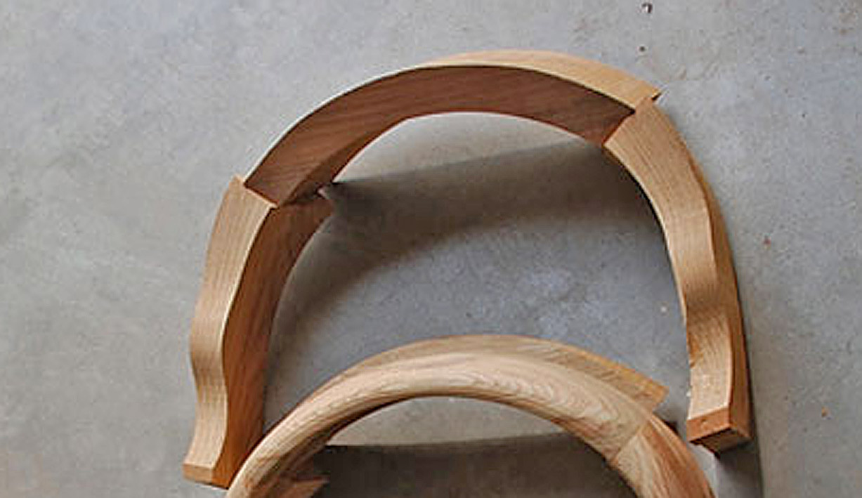
But look at the first photo in that sequence - the back is angled into the arms. Wonderful - less to carve!
The arms need to be shaped from blocks 90mm high, so I got busy laminating ...
And while this was drying, time was spent on getting the profile for the side of the arms ...
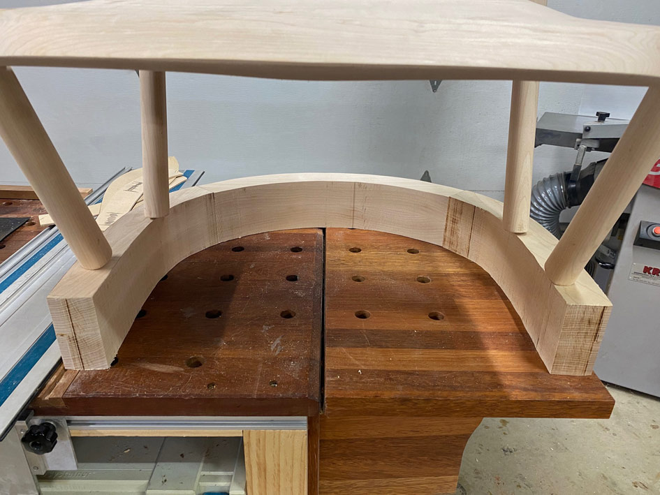
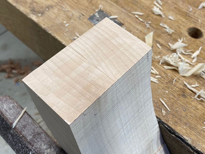
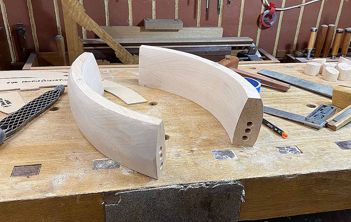
There's a photo on the wall behind against which to compare. Also, a first look at the completed through tenons.
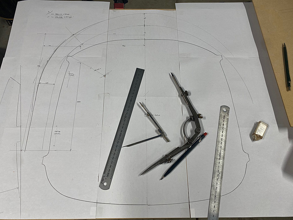
That's the easy stuff. Time to design the arm and back profiles.
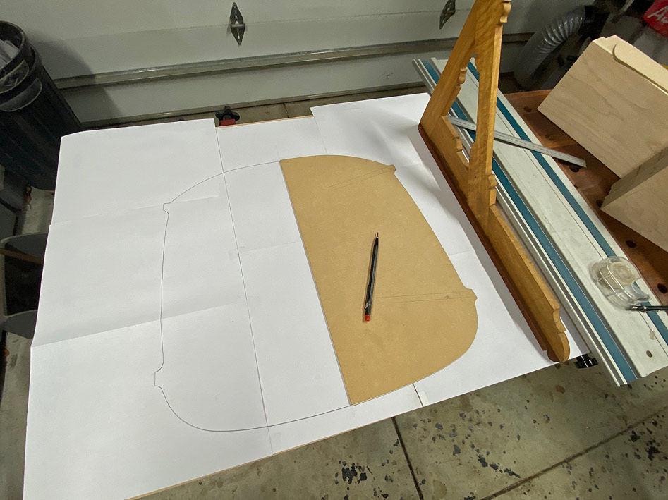
We start with a seat ...
... to use to frame around ...
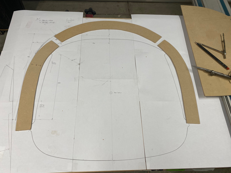
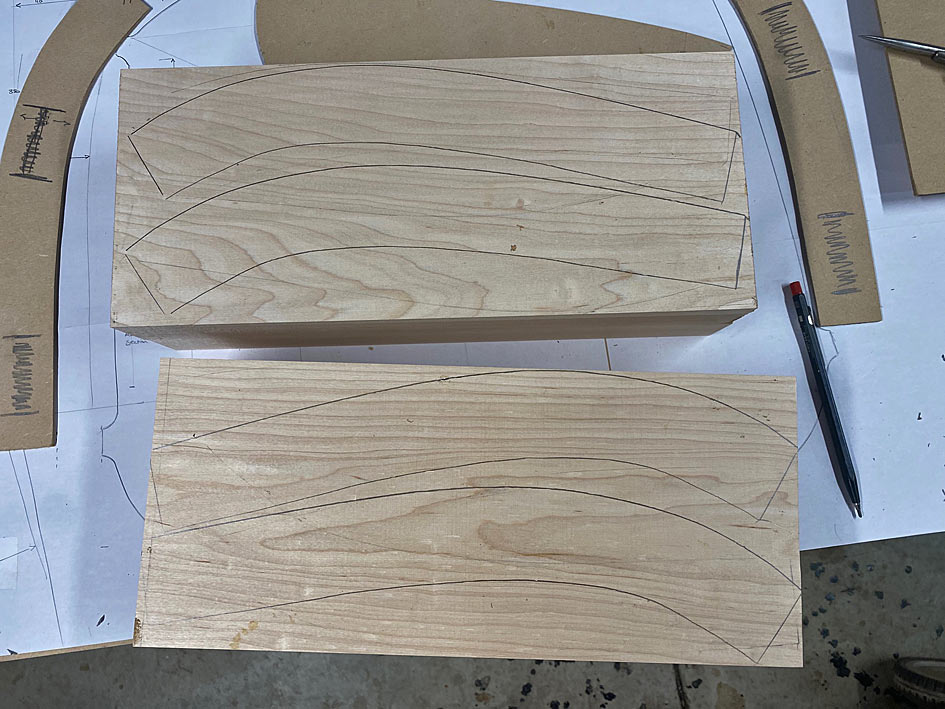
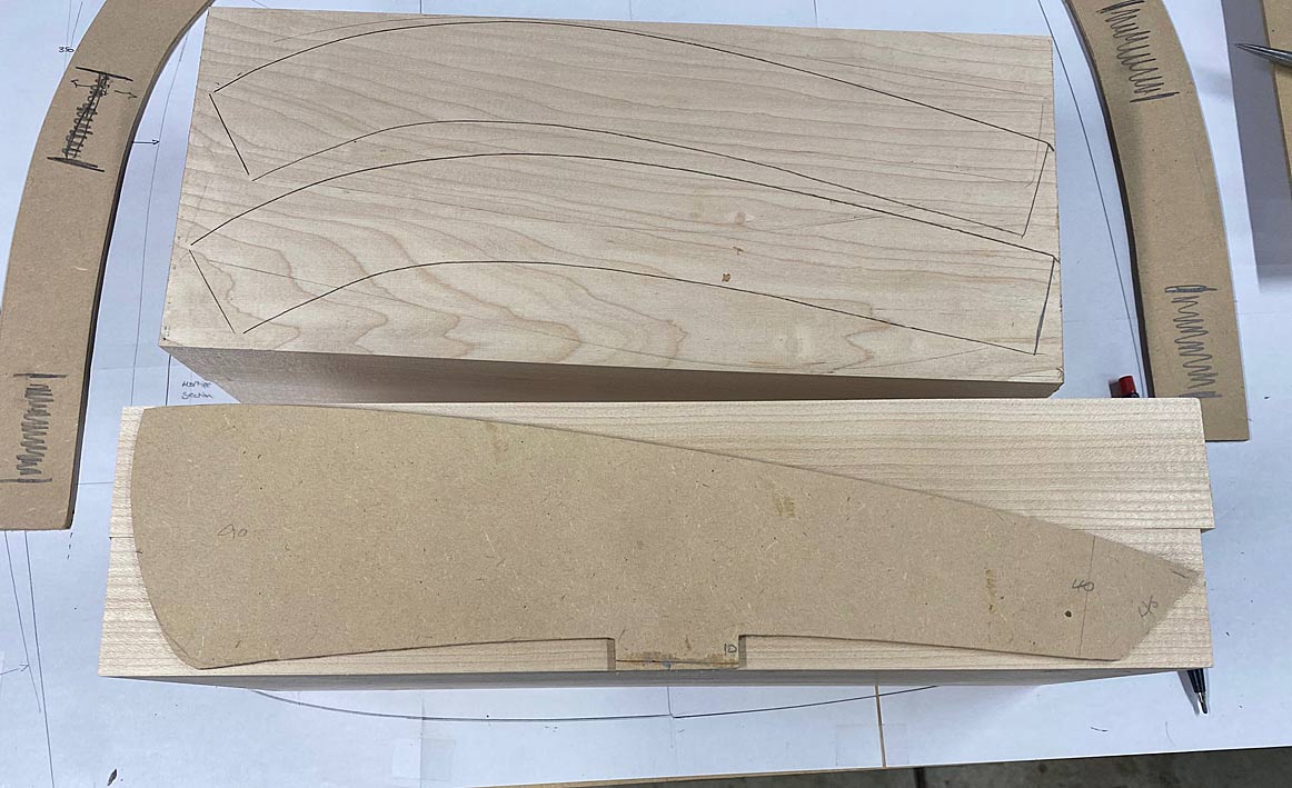
After much back-and-fro drawing, rubbing out, re-drawing, and transfering to MDF for templates ...
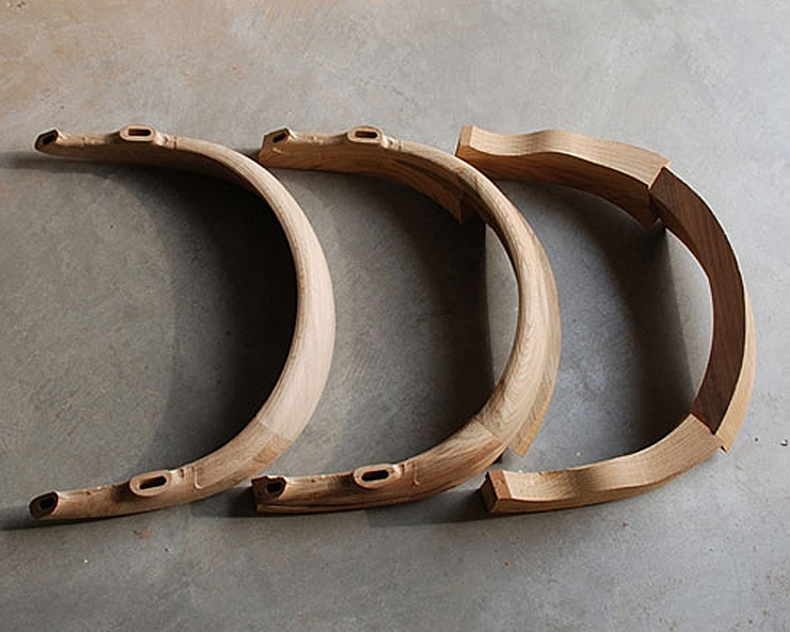
Each of the blocks (seen beng glued up earlier) create four arm blanks ...
Here is the side elevation ...
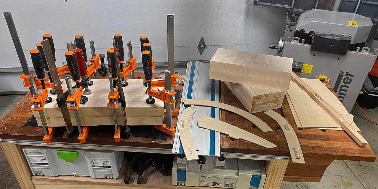
Wood for the backs came from sawing up this 3m long board ...
And, for now, the backs are laminated and drying alongside the other blanks and templates ..
Tomorrow I shall begin cutting it all up, and joining pieces together.
A question for all is how you might connect/join the arms with the legs? Note that the back will be joined angled to the sides, as per the photo.
Regards from Perth
Derek
Contributor
Derek, Fascinating project. Having done a few Maloof rockers, and armed with your guidance set forth herein, i think i will try one of these. Very generous of you to share so much of the detail. Thank you kindly.
Carry on, and Slainte, Patrick
[OP]
Contributor
Thanks Patrick. I hope you post your work here.
Regards from Perth
Derek
[OP]
Contributor
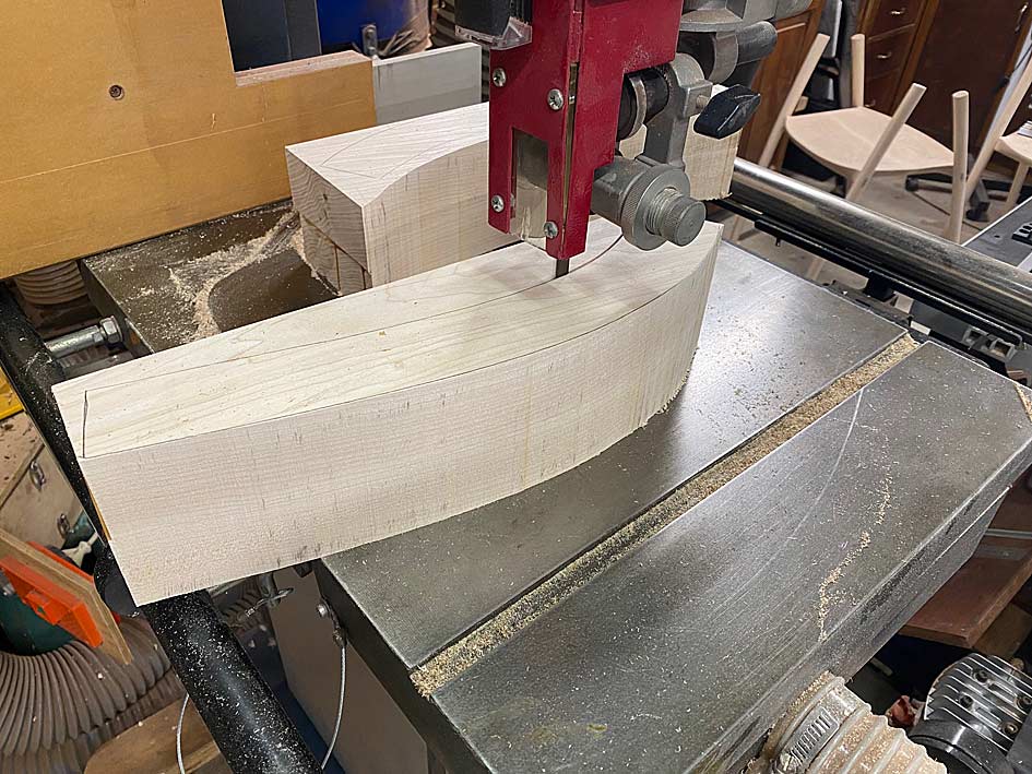
Here is the work done today, which was preparing the arms before shaping. Critical work, and the day went well. This was mainly due to working methodically. Looking back it all seemed so logical and straightforward, but it didn't feel this way before hand.
The first task was to bandsaw all the blocks of wood into shape, having outlined the parts with the templates.
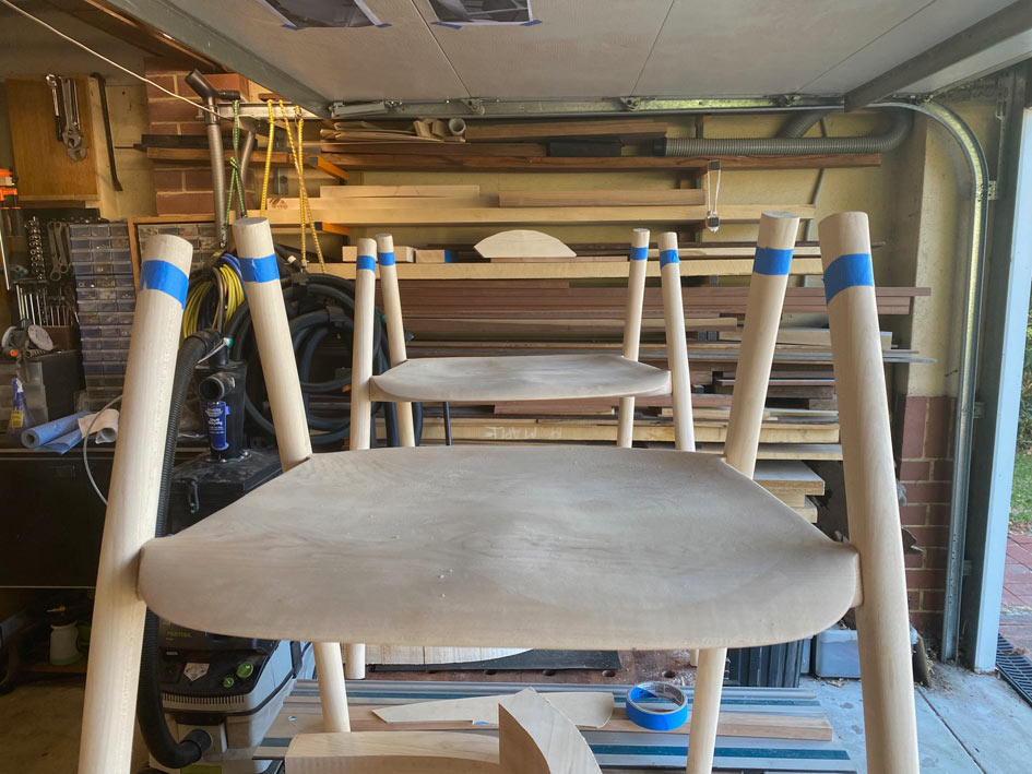
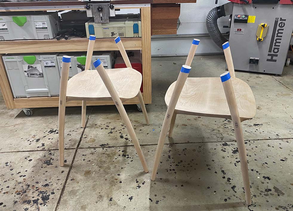
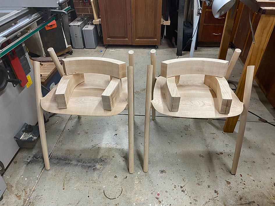
Lining up the arm parts for two chairs, three for each ...
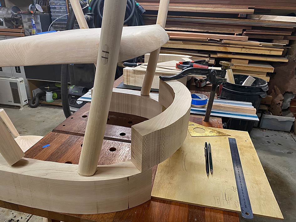
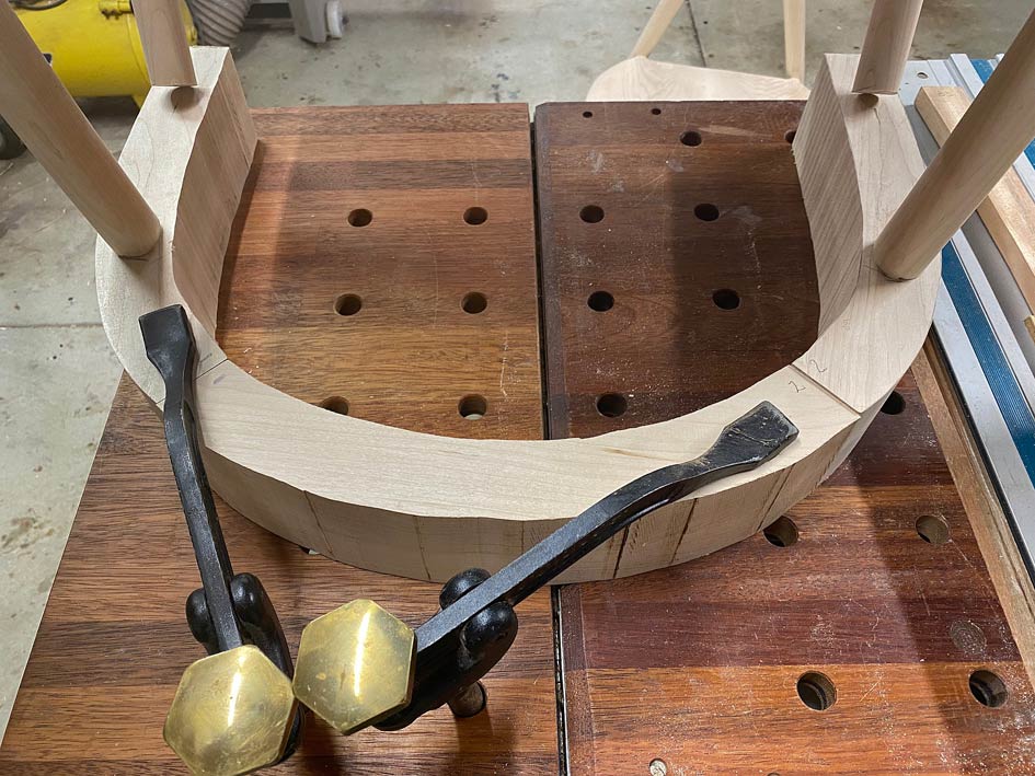
At first I thought I would clamp them together and balance the lot on top of each chair ... no, that would be silly!The chairs were turned upside down on the arms ...
This revealed that the spread of the arms was a little too wide. The arm supports need to be centred on the arm rests ...
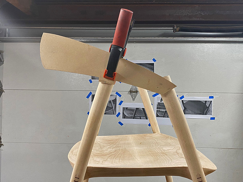
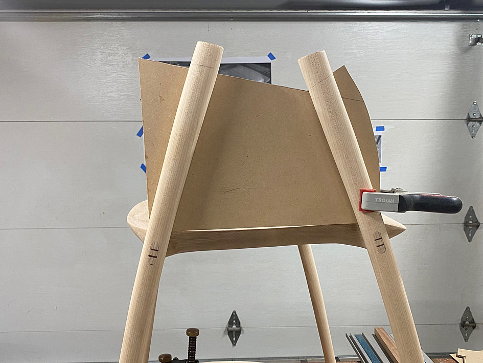
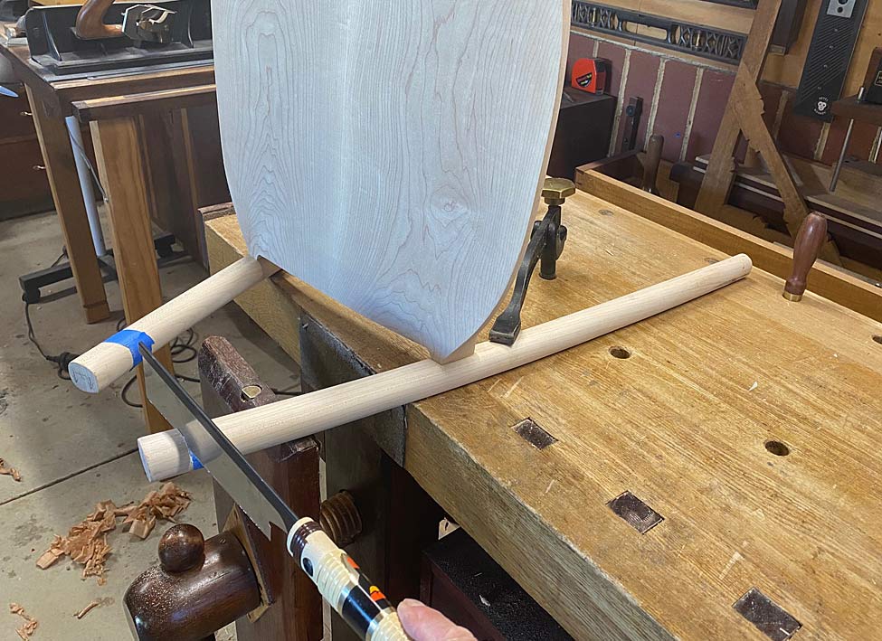
Before adjusting this, the next stage needed to be to cut the arm supports to length. To do this, first the template for the arm elevation was positioned ...
... and then a template was made to position this ...
This allowed all the arms supports to be marked on both sides ..
.. and marked with blue tape ...
The excess is sawn away ...
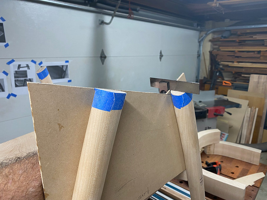
The template also enables the accuracy of the saw cuts to be checked, and for square. This will need to be fine tuned later, but good for now ...
The underside of the arms are marked so the positions on each will be the same, and the overhang at the rear was roughly calculated. Again, this will be adjusted after the arms parts are joined.
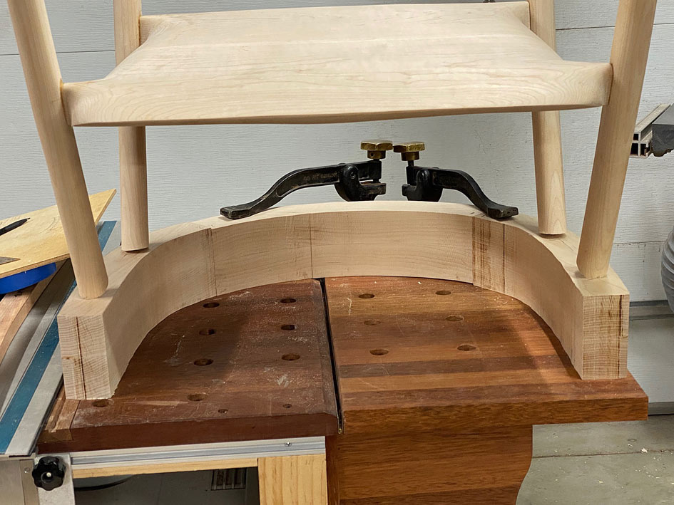
Now the top rail can be positioned for sizing ..
It is marked for sawing ...

[OP]
Contributor
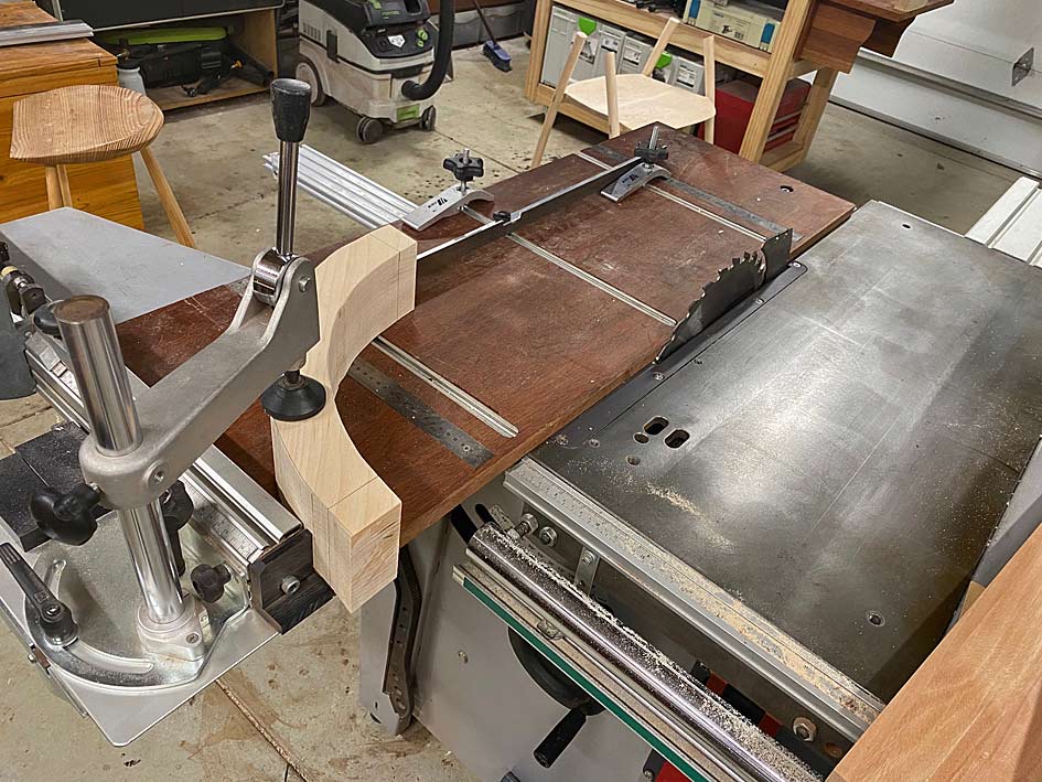
Aligned on the slider ...
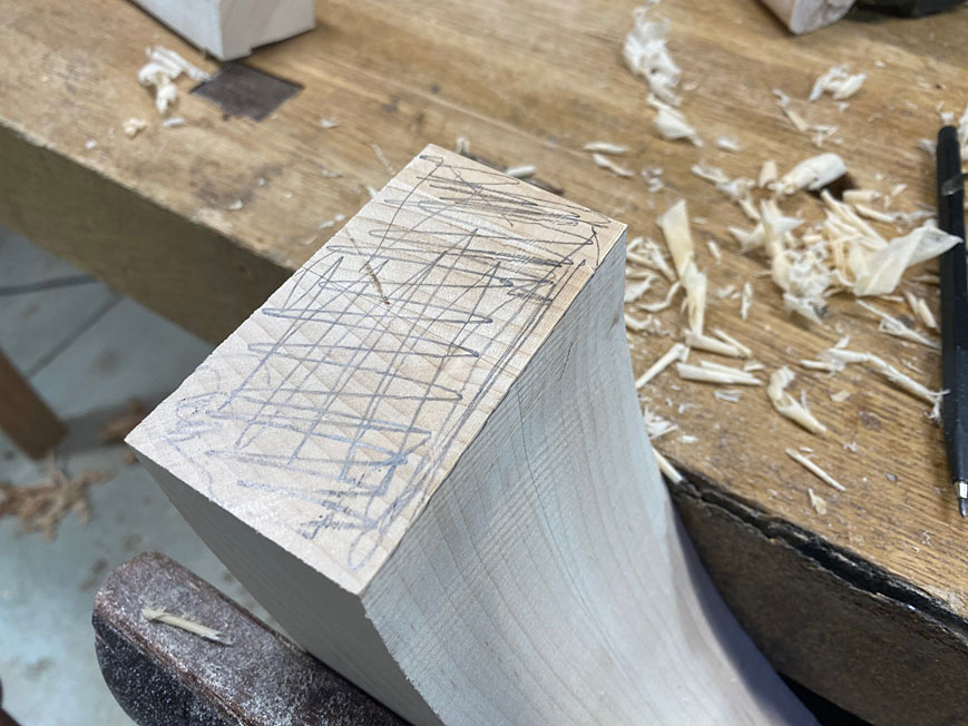
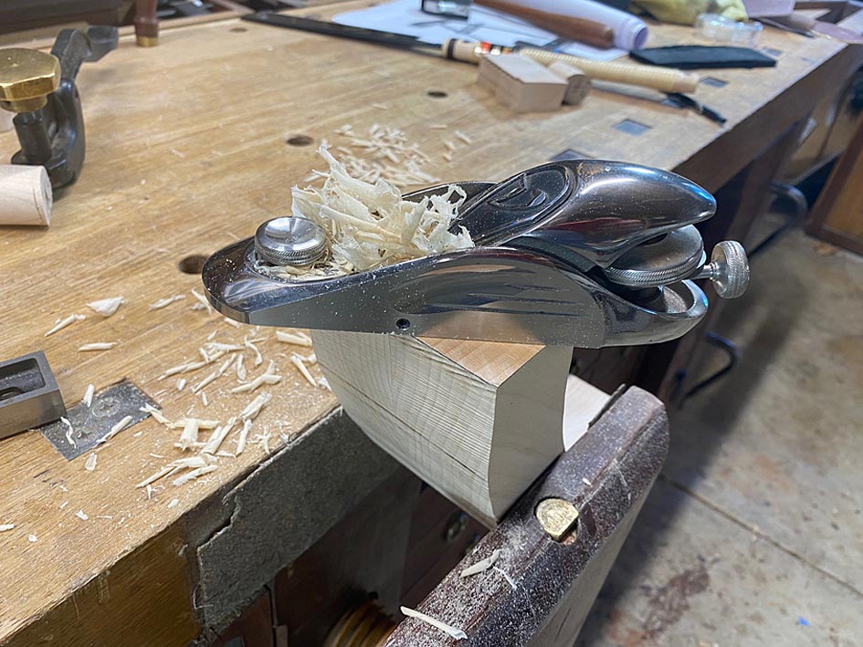
All the ends of the arms are squared this way, however the saw has a maximum cut height of 75mm and these parts are 90mm. This leaves 15mm to saw away with a hand saw, and then clean up with a block plane. This clean up is important as it is also jointing for the parts to fit together gap-free ...
The arm parts are ready to fit together ...
And all done for the day ...
Regards from Perth
Derek
Contributor
Derek,
It's a real joy to see the progress on your chairs.
When I had to make a similar angled back to arm joint, I ended up using several 1/8" x 2" splines. I was afraid to even attempt the tapered finger joints as you did on your Wegner chair reproduction.Originally Posted by Derek Cohen

I wonder if splines between the arm to leg joint with similar wood as you used for the tenon wedges would work well.
Look forward to seeing more.
Regards,
Jeff
Contributor
Derek, you wrapped blue tape around the tops of the legs to guide the cut - how did you know the line to mark?
Seems like this would be very difficult to get right. The template use used helped but there was still a lot to get on the money.
[OP]
Contributor
Mark, first I ran lines on each side of the seat support (legs) using a template - which was placed on both sides of the seat supports ...
I did have to estimate the ends where it was not possible to mark.
Sawing was fine for about 6/8 of the seat supports. On two I went a little off course, but then used a rasp to level it - again using the template to determine where to do this ...
Does that answer your question?
Regards from Perth
Derek
Contributor
Yes, though I'm glad I'm not doing it.
[OP]
Contributor
Arms - part 1
The key piece is the top rail, and the key element here is the rear curve. Here it is smoothed on the belt sander. It will be a reference side for marking curves ...
The angles I have had to guestimate have been the tilt, front and rear, of the top rail. This is what I came up with ...
The plan is to join the arms using dowels. The Rule of Thirds applies. 3 x 3/8" dowels (3/8" = 9.5mm, which is close to the 10mm tenons used previously). Why dowels? Because they are easier to position accurately without a reference edge.
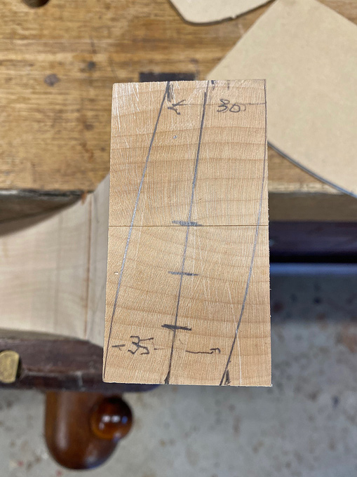
Since a large amount of waste will be removed from the top rail and arms, through shaping, the dowels need to be positioned where they will not be cut into. The three marks on the ends of the top rail are the position for the dowels. The wooden block was a quick guide to drill vertical as it needed to be done freehand ..
The only complication was that I had 6mm dowel centre points. It would have been easier if they were 3/8". Nevertheless ...
Drilled for 3/8" dowels in Jarrah (I have a bucket of them), each close to 50mm (2") in length.
Everything is still a rectangle at this stage ...
The inside face of the top rail is shaped ...
It is at this point that I have a re-think about the curve of the rear - it is not a fair curve and enough curve when compared with the photos of the DC 09 chair. The re-drawn curve on the left looks correct to me now, and this is what we will go with ...
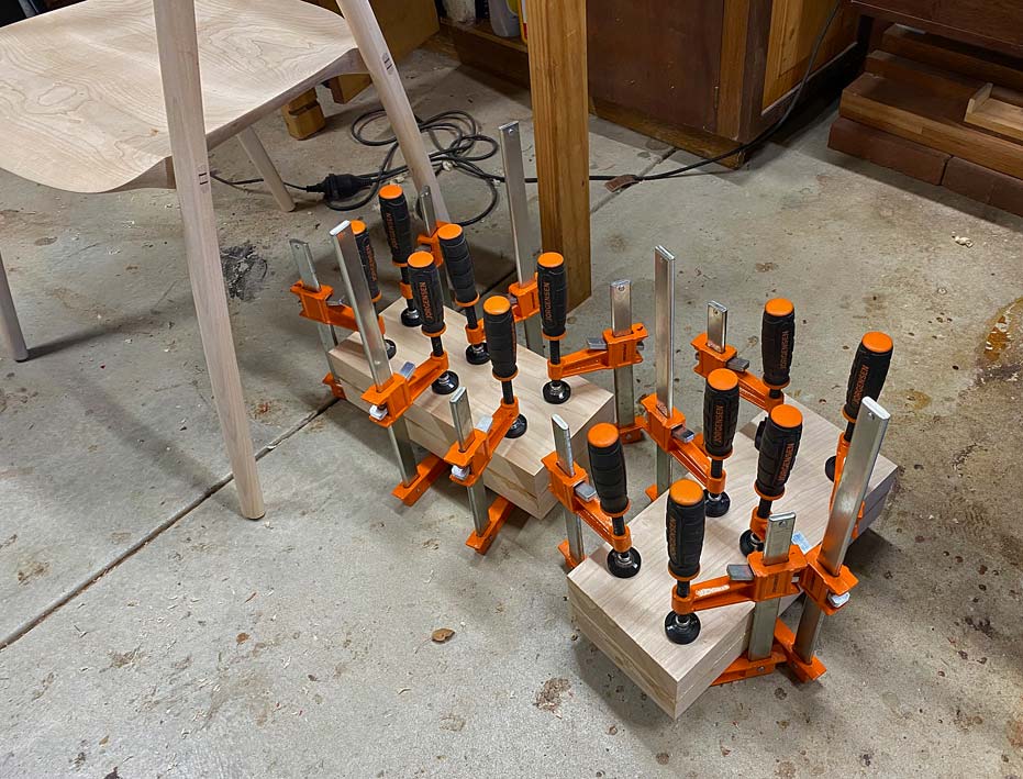
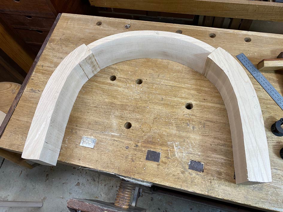
The parts are joined up as a loose fit (using undersized dowels)...
The arm/rail combination is now placed on the arm supports and adjusted to the front and rear to determine the rear overhang and position for the front joint ..

[OP]
Contributor
The template I made up earlier is used to trace out the side elevations. The shaping here is approximate. The main goal is to establish the length of the arms and from arm support joint ...
A little detail of interest: the height cut is slightly more than the front joint triangle would suggest as the final shaping requires a little extra meat to end in a curve ...
This is now sawn to shape, except for the underside of the arm, as the mortise/tenon area needs to be determined separately for each arm ...
Tomorrow will begin the final shaping and, hopefully, glue up of the arms.
Regards from Perth
Derek
 Contributor
Holy sh** Derek! This is looking so good! What a complicated yet interesting build. You're getting so close to finish line yet still so much to work on and think about. Great build thread and look forward to seeing it through.
Contributor
Amazing
jtk
"A pessimist sees the difficulty in every opportunity; an optimist sees the opportunity in every difficulty."
- Sir Winston Churchill (1874-1965)
 Posting Permissions

 Reply With Quote