Pretty cool little touch that I doubt most people will notice but would notice if it wasnt there. Coming together nicely.


 Contributor
Pretty cool little touch that I doubt most people will notice but would notice if it wasnt there. Coming together nicely.
 [OP]
Contributor
[OP]
Contributor
Which one are you referring to, Tony? And thanks.
Kind regards
Derek
Contributor
The flat on the leg
Contributor
Those are really looking good, Derek. Had you considered using hidden wedges on the tenon, into the seat? That might've made future re-glues less likely; or perhaps have been too likely to split the seat?
[OP]
Contributor
Thanks Greg ... and welcome to SMC.
I did think of pinning the tenons, but decided against this as it is likely to just damage them. Glue should be fine.
Regards from Perth
Derek
[OP]
Contributor
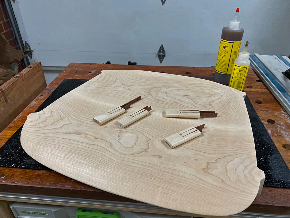
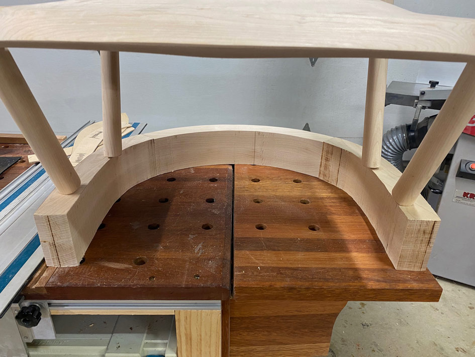
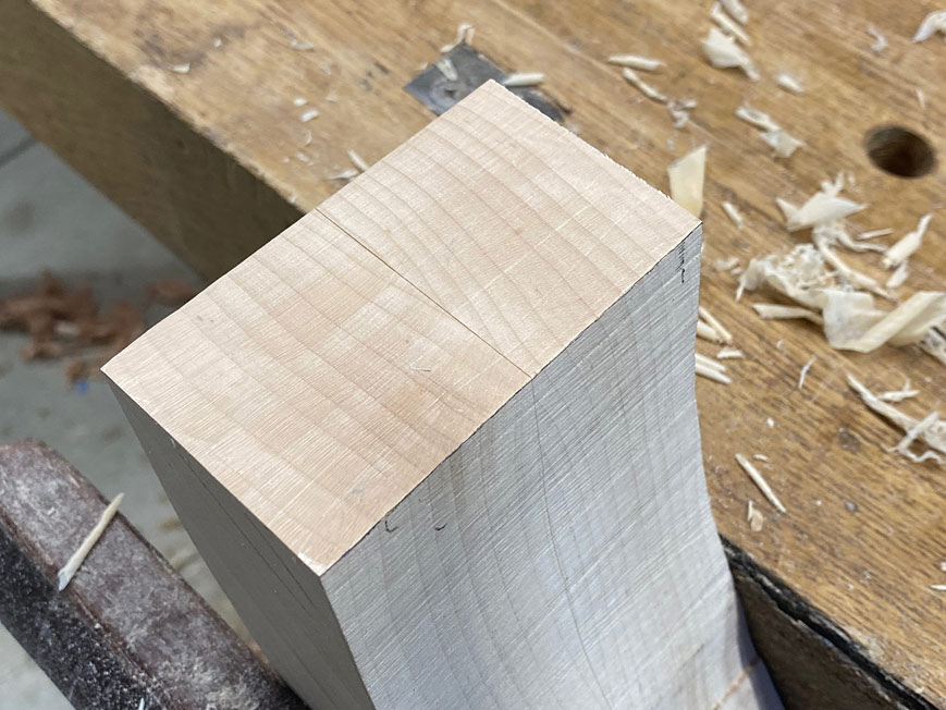
A note about wedges
This is a cross post from the Australian forum, where I was asked for more information about the wedged through tenons.
I am not sure if the photo provided must detail, but the wedges are tapers, but also long and skinny ...
They both fill the slot - which is full of glue - and create a wedging action, firmly pushing the tenon edges against the glued insides of the mortise. The mortises, both in the seat and legs was 30mm long. Most were exact, some of the legs were a little under a mm long. A little filing for all to create this tiny gap - it does not have to be more. The glue is enough and the wedges are security. Interestingly, this appears to be the same in the original chair, with the exception that they added a chamfer for the end of the wedge. I've never seen this before ..
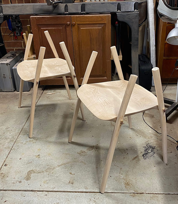
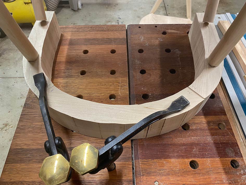
In addition to the wedged legs (I am trusting that the small amount of taper inside the mortises will add an extra layer of solidness), the arm/back structure adds stiffness and resists the legs wracking/moving. It is akin to triangulation of the construction (not really triangles, of course).
I have removed the clamps and the structure is really stiff already - I will wait until Lynndy is out of the way to take some photos. She-Who-Must-Be-Obeyed is keeping a steely eye on my "taking it easy" today![Explanation: I was in hospital yesterday for an op on my left torn patella]
Later:
I snuck into the workshop to unclamp the glue up. Lynndy caught me! But she then asked to sit on one of the chairs (sans the arms and back). She did so gently, and then with all her weight (55Kg). The seats did not even sigh, and nothing moved. She proclaimed the seat very comfortable. Yay!
Tenons and wedges yet to be cut and levelled ...
Regards from Perth
Derek
Contributor
Wow Derek stellar work. It’s been a while since I’ve poked my nose under the tent and a had a couple of pages to catch up on. Hope your surgery went well and you are recovering nicely. The chairs are going to be beautiful, heck they are beautiful now.
Jim
Ancora Yacht Service
 Contributor
Great work. Could it be the chamfers for the end of the wedges was to accommodate a more aggresive wedge? A long, glued tongue would hold the wedge while the part in the chamfer would taper the wedge more in a mortise.
jtk
"A pessimist sees the difficulty in every opportunity; an optimist sees the opportunity in every difficulty."
- Sir Winston Churchill (1874-1965)
[OP]
Contributor
Jim, I can imagine the "what" and even the "why", but struggle to understand the reason it was considered necessary.
Regards from Perth
Derek
Contributor
It could have been decorative with a wider contrasting band across the tenon. Maybe even a small wedge in the wedge to punch it up a bit.
It could have also allowed for more taper in the mortise.
Worst of all would be, "that's how my teacher always told me to do it."
jtk
"A pessimist sees the difficulty in every opportunity; an optimist sees the opportunity in every difficulty."
- Sir Winston Churchill (1874-1965)
[OP]
Contributor
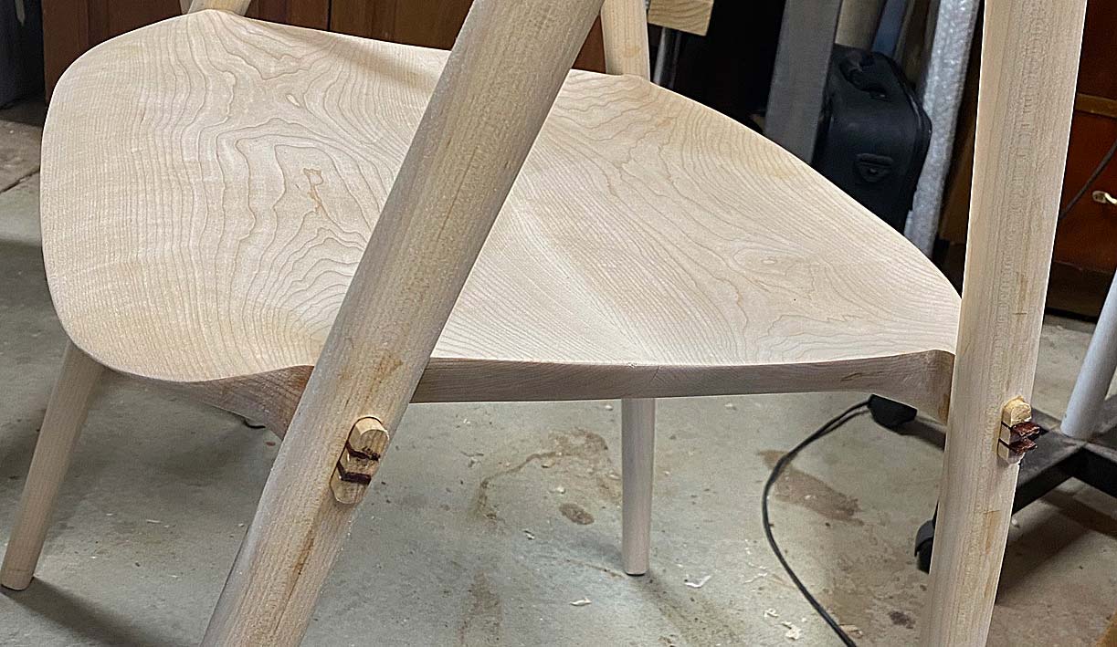
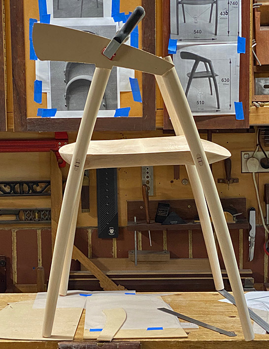
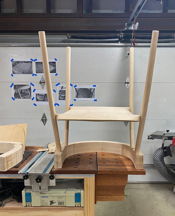
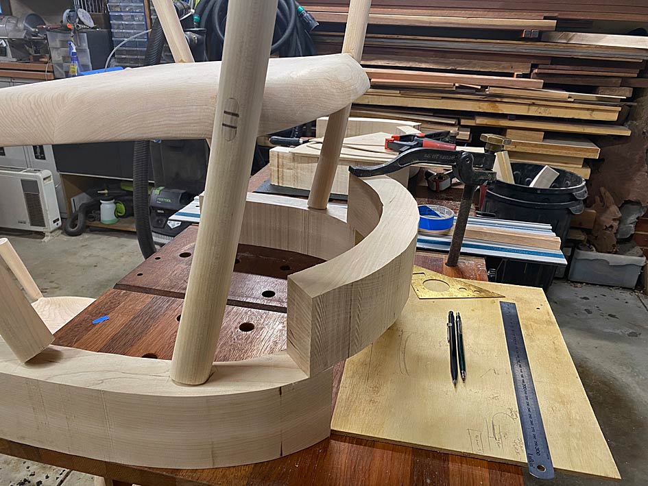
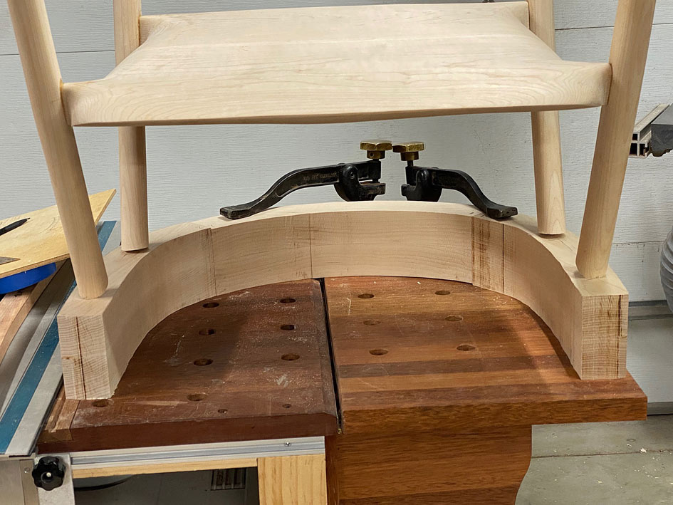
Beginning the arms and back
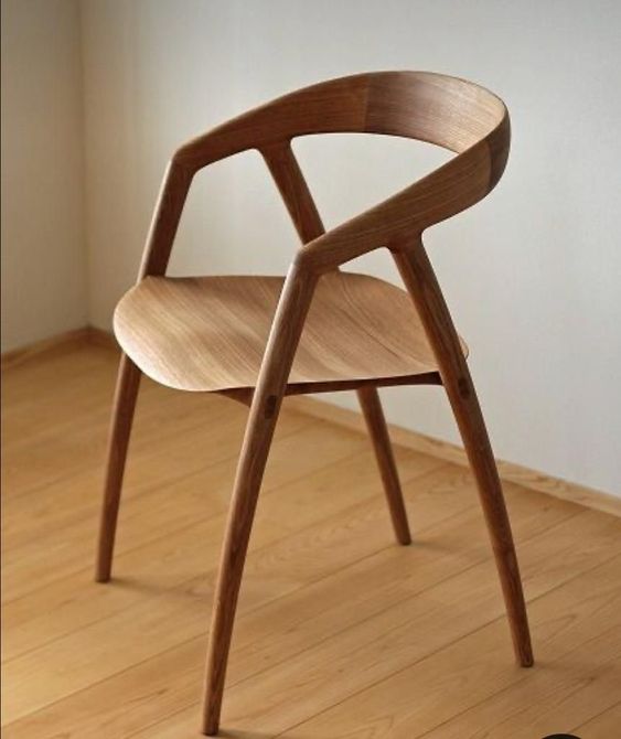
The legs and seats are done and it is time to move to the arms and backs. Once again, the chair to provide a context of where we are headed ...
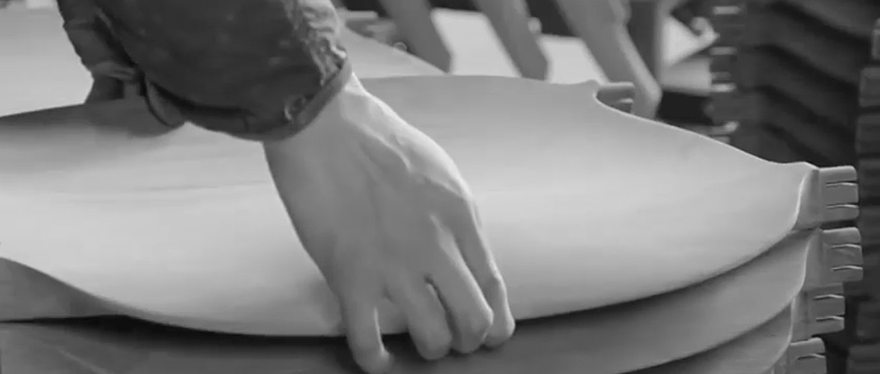
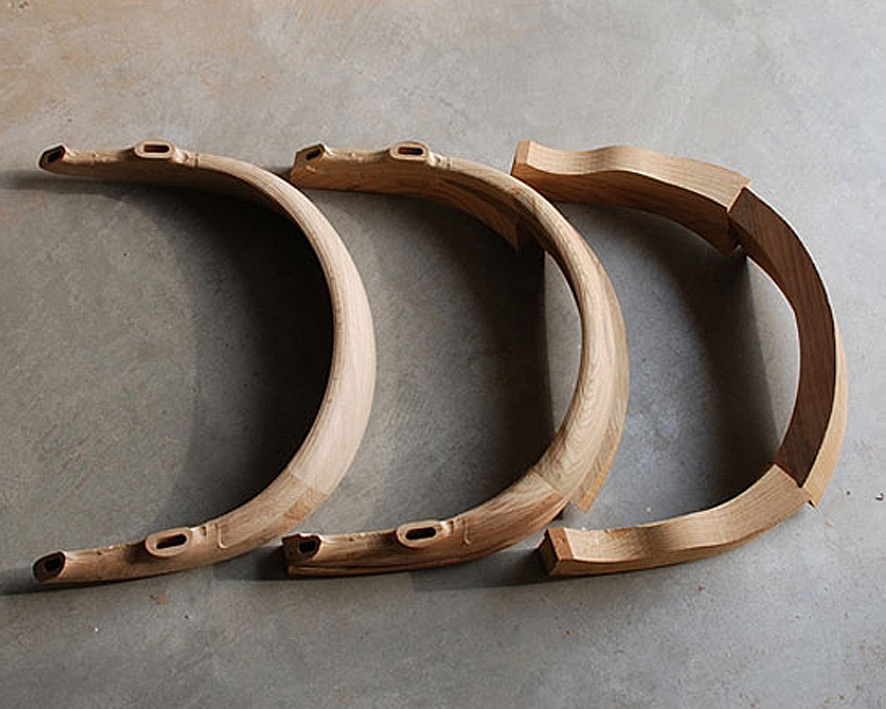
I was fortunate to find a few photos on the Web showing the development of the arms/back, which provided some insight into how to construct this ...
The construction sequence that was really helpful was this (note these are from the underneath) ...
While this makes it all appear accessible, my experience building a Hand Wegner chair prepared me for the large chunks that make up the two arms and the back ...
Giant slabs and lots of carving (since, unlike the factory, I do not have a CNC machine) ...
But look at the first photo in that sequence - the back is angled into the arms. Wonderful - less to carve!
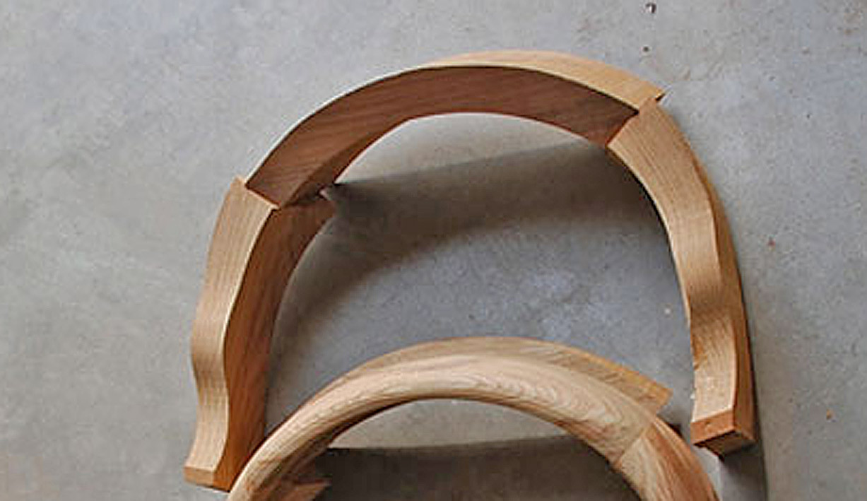
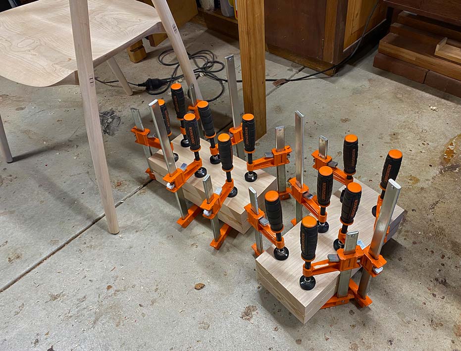
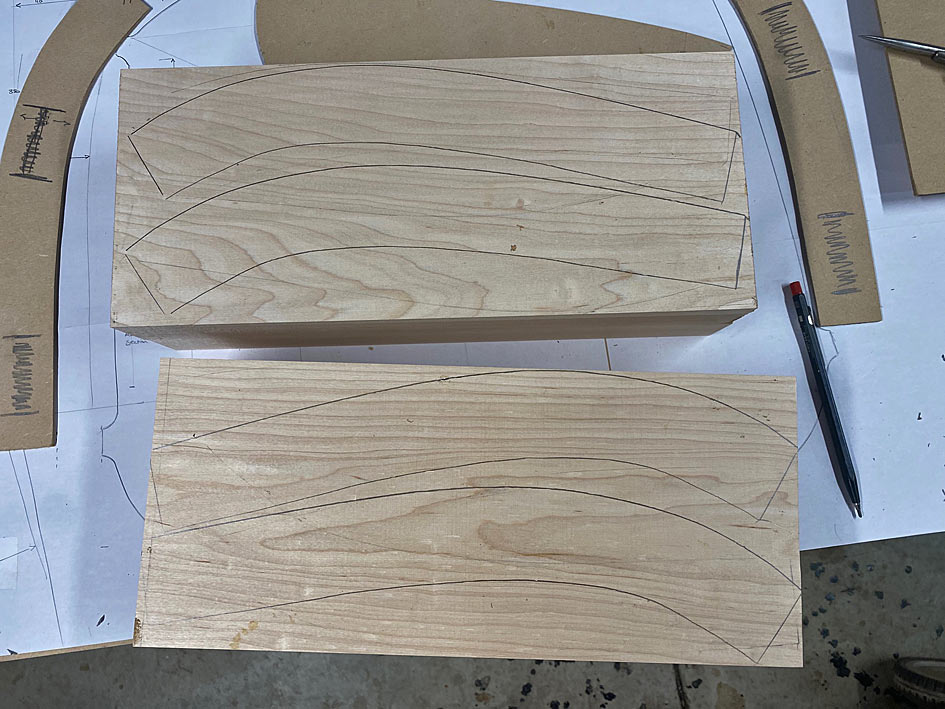
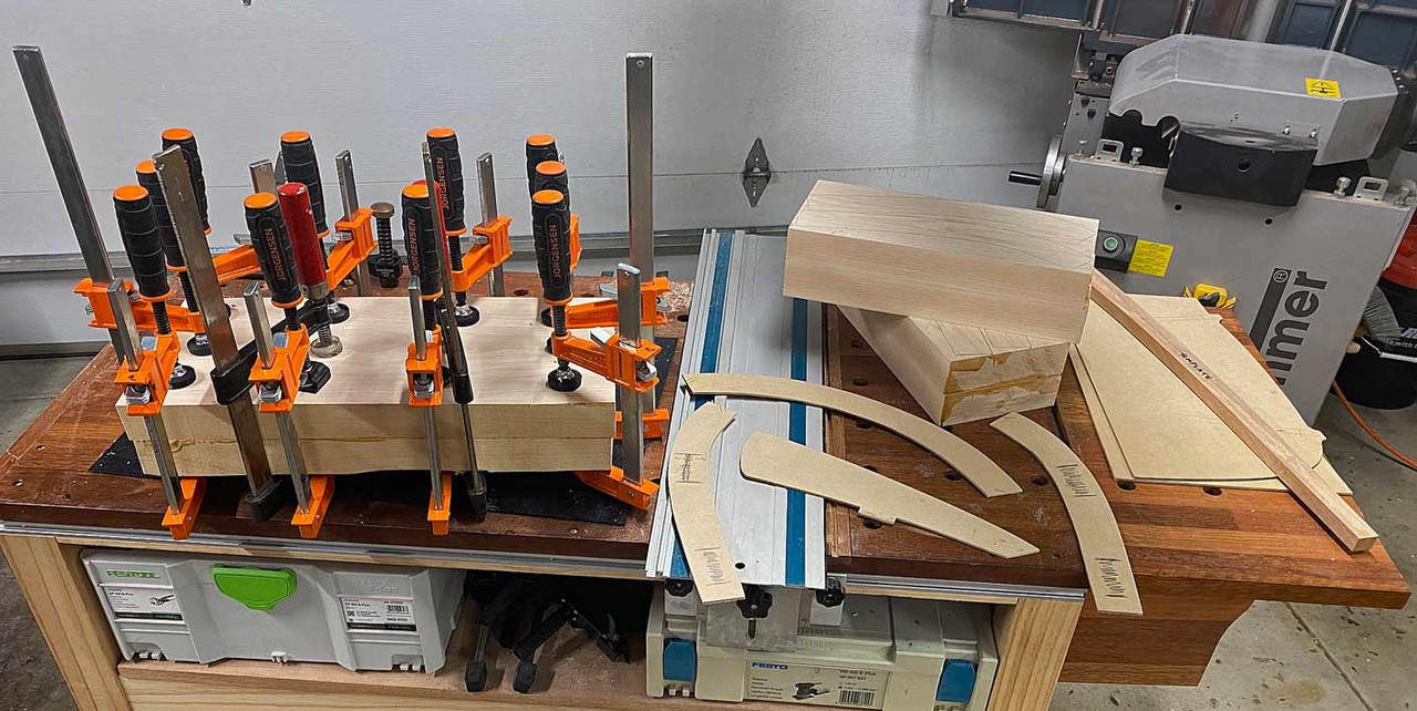
The arms need to be shaped from blocks 90mm high, so I got busy laminating ...
And while this was drying, time was spent on getting the profile for the side of the arms ...
There's a photo on the wall behind against which to compare. Also, a first look at the completed through tenons.
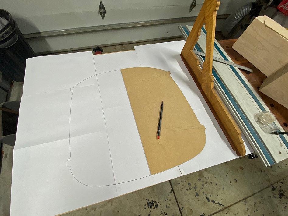
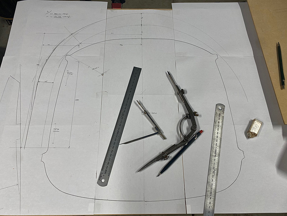
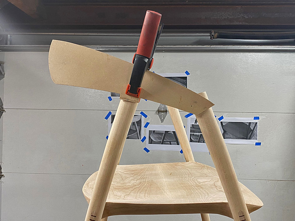
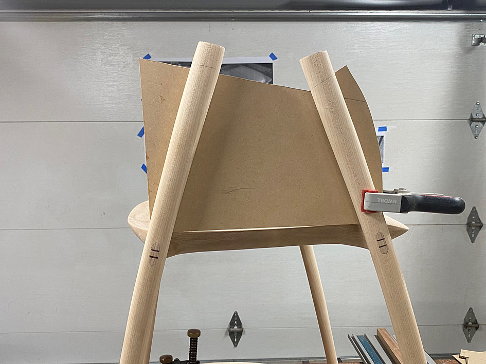
That's the easy stuff. Time to design the arm and back profiles.
We start with a seat ...
... to use to frame around ...
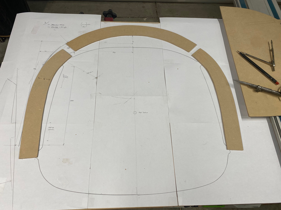
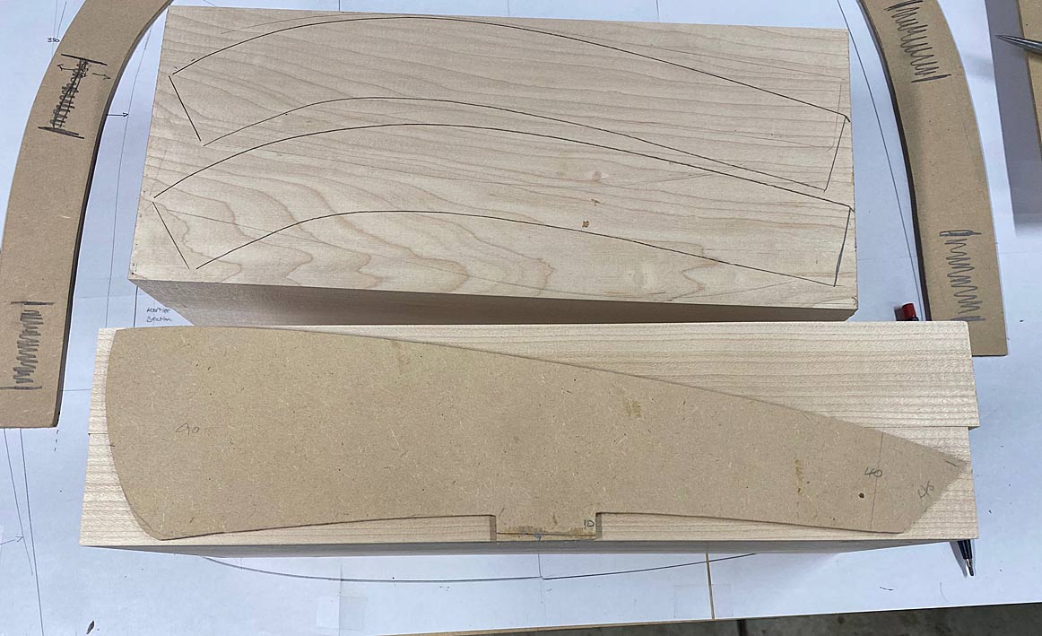
After much back-and-fro drawing, rubbing out, re-drawing, and transfering to MDF for templates ...
Each of the blocks (seen beng glued up earlier) create four arm blanks ...
Here is the side elevation ...
Wood for the backs came from sawing up this 3m long board ...
And, for now, the backs are laminated and drying alongside the other blanks and templates ..
Tomorrow I shall begin cutting it all up, and joining pieces together.
A question for all is how you might connect/join the arms with the legs? Note that the back will be joined angled to the sides, as per the photo.
Regards from Perth
Derek
 Contributor
Derek, Fascinating project. Having done a few Maloof rockers, and armed with your guidance set forth herein, i think i will try one of these. Very generous of you to share so much of the detail. Thank you kindly.
Carry on, and Slainte, Patrick
[OP]
Contributor
Thanks Patrick. I hope you post your work here.
Regards from Perth
Derek
[OP]
Contributor
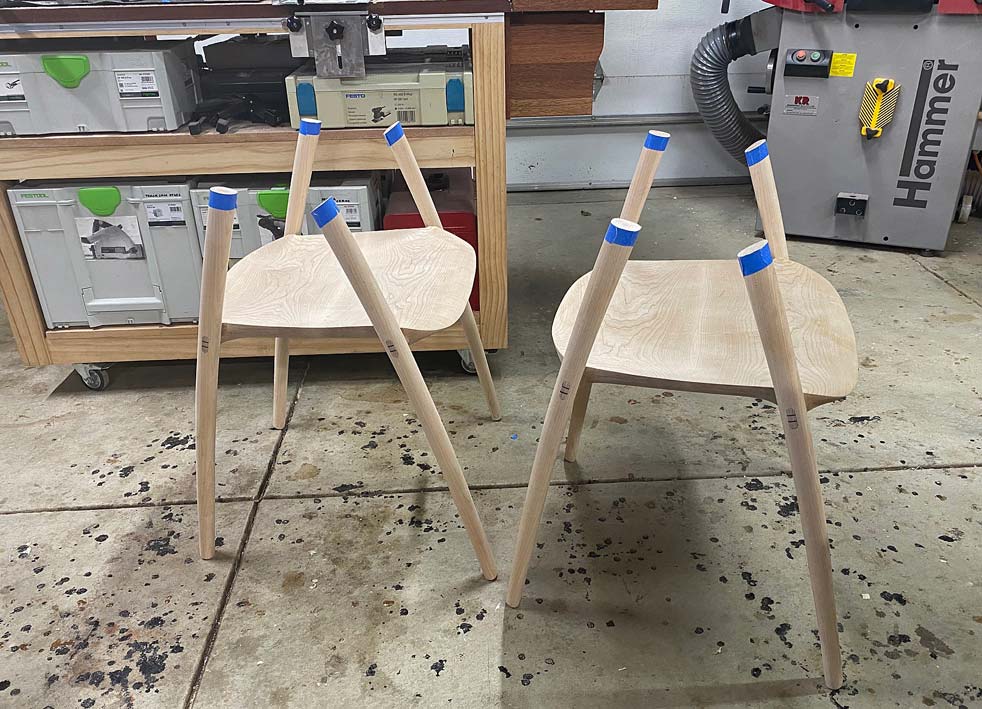
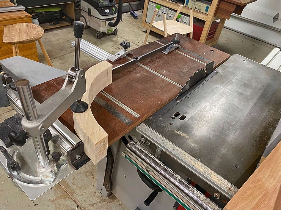
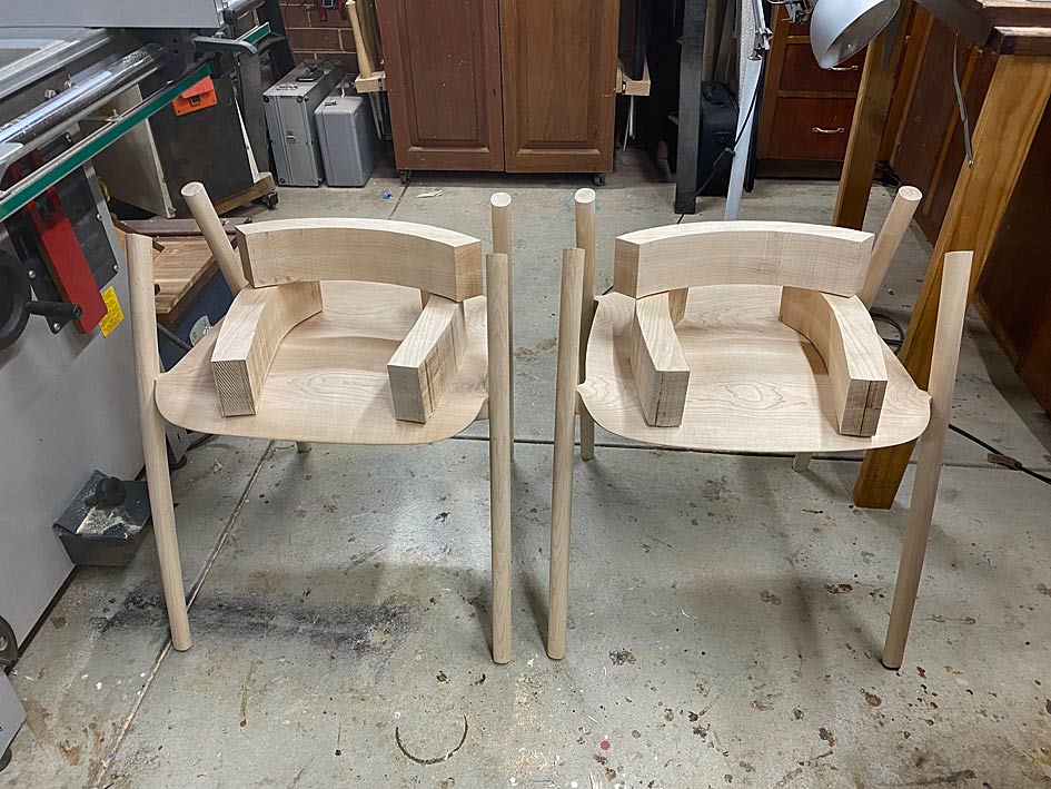
Here is the work done today, which was preparing the arms before shaping. Critical work, and the day went well. This was mainly due to working methodically. Looking back it all seemed so logical and straightforward, but it didn't feel this way before hand.
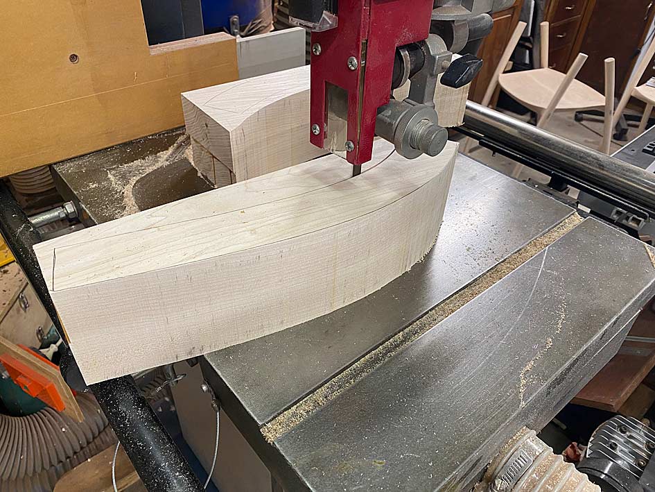
The first task was to bandsaw all the blocks of wood into shape, having outlined the parts with the templates.
Lining up the arm parts for two chairs, three for each ...
At first I thought I would clamp them together and balance the lot on top of each chair ... no, that would be silly!The chairs were turned upside down on the arms ...
This revealed that the spread of the arms was a little too wide. The arm supports need to be centred on the arm rests ...
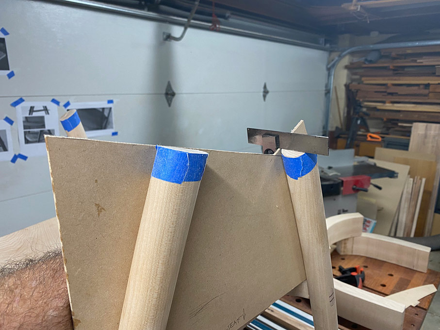
Before adjusting this, the next stage needed to be to cut the arm supports to length. To do this, first the template for the arm elevation was positioned ...
... and then a template was made to position this ...
This allowed all the arms supports to be marked on both sides ..
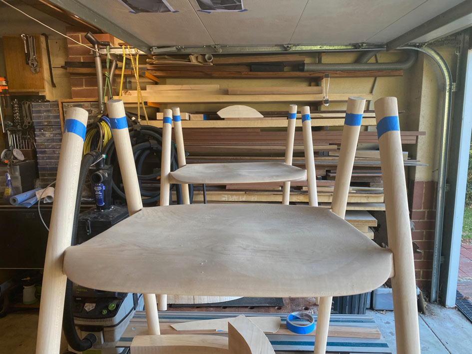
.. and marked with blue tape ...
The excess is sawn away ...
The template also enables the accuracy of the saw cuts to be checked, and for square. This will need to be fine tuned later, but good for now ...
The underside of the arms are marked so the positions on each will be the same, and the overhang at the rear was roughly calculated. Again, this will be adjusted after the arms parts are joined.
Now the top rail can be positioned for sizing ..
It is marked for sawing ...

[OP]
Contributor
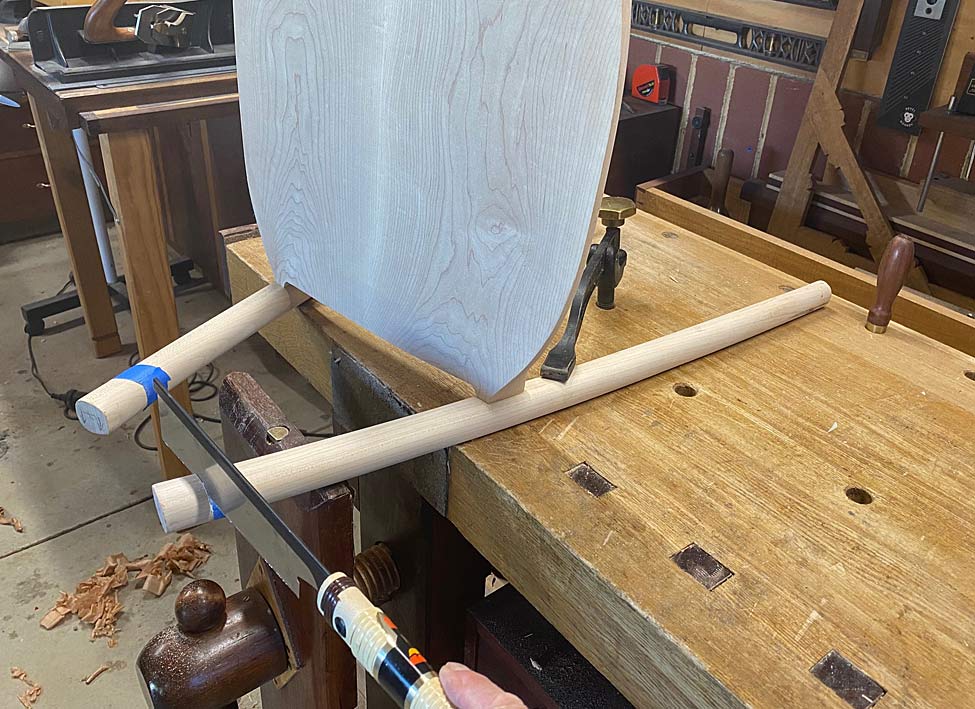
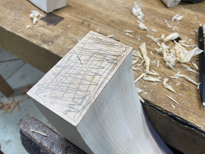
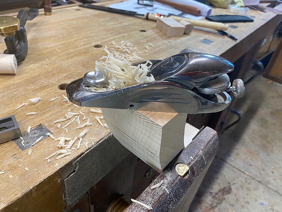
Aligned on the slider ...
All the ends of the arms are squared this way, however the saw has a maximum cut height of 75mm and these parts are 90mm. This leaves 15mm to saw away with a hand saw, and then clean up with a block plane. This clean up is important as it is also jointing for the parts to fit together gap-free ...
The arm parts are ready to fit together ...
And all done for the day ...
Regards from Perth
Derek
 Posting Permissions

 Reply With Quote