Page 2 of 2 FirstFirst 12
Results 16 to 23 of 23

Thread: New-old saw till

  1. #16
    Join Date
    Feb 2004
    Location
    Perth, Australia
    Posts
    9,494
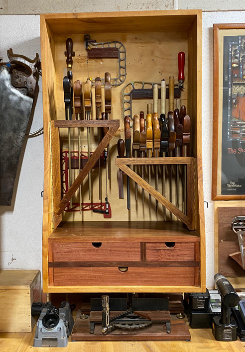
    Cory, the saws each have a dedicated slot that holds the back in two places, making them very secure ...

    These were made this way, creating the ideal depth and width for each back ...


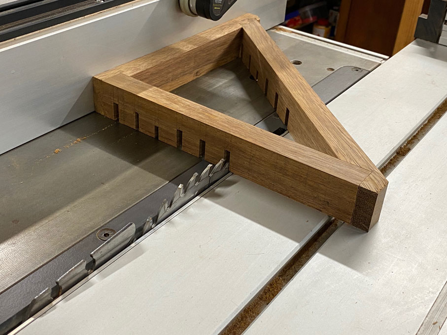
    These slots are for the brass backs.

    Over the front a solid section is glued, and this is slotted for the blade. When the back is slid down into the slot, they are effectively locked into position.


    The "gates" are locked from the outside of the cabinet, so they do not swing freely.

    If you look carefully here (at the sides), you will see two hex keys (one on each side). Just pull one out half way to release a gate.


    Regards from Perth

    Derek
    Last edited by Derek Cohen; 02-02-2022 at 9:48 AM.

  2. #17
    Join Date
    Jul 2006
    Location
    McKinney, Texas
    Posts
    84
    Thank you, very good

  3. #18
    Join Date
    Nov 2020
    Location
    East Cost
    Posts
    205
    Derek, is there a magnet or something in the triangular swinging pieces? Or is it friction fit? I was contemplating something like this, but all the prototypes had saws occasionally falling out when swung. Couldn't find a good and simple solution to this.

  4. #19
    Join Date
    Mar 2013
    Location
    North Alabama
    Posts
    548
    Quote Originally Posted by Jack Dover View Post
    Derek, is there a magnet or something in the triangular swinging pieces? Or is it friction fit? I was contemplating something like this, but all the prototypes had saws occasionally falling out when swung. Couldn't find a good and simple solution to this.
    Where Derek says this...
    Quote Originally Posted by Derek Cohen View Post
    Over the front a solid section is glued, and this is slotted for the blade. When the back is slid down into the slot, they are effectively locked into position.

    ...he means this.
    Keepers.jpg

    I wondered the same thing as you at first and didn't notice Derek's solution until he explained it.
    Chuck Taylor

  5. #20
    Join Date
    Feb 2004
    Location
    Perth, Australia
    Posts
    9,494
    I’ll try and take a photo of this and post it.

    Regards from Perth

    Derek

  6. #21
    Join Date
    Feb 2004
    Location
    Perth, Australia
    Posts
    9,494
    Here can be better seen the section that runs across the front of the grooves for the saw back. This was glued and screwed as a single board to the front, and then a kerf added for the saw blade ....


    As now seen, the saw back is trapped in the groove. The lower groove is left open.


    I will add that the same system was used for the Japanese saws inside the cabinet. Some required openings for the saw backs/spines, while a few did not. I simply drilled and chiselled these out.

    Regards from Perth

    Derek
    Last edited by Derek Cohen; 02-02-2022 at 10:57 PM.

  7. #22
    Join Date
    Jan 2019
    Location
    Fairbanks AK
    Posts
    1,566
    Quote Originally Posted by Derek Cohen View Post
    Here can be better seen the section that runs across the front of the grooves for the saw back. This was glued and screwed as a single board to the front, and then a kerf added for the saw blade ....

    As now seen, the saw back is trapped in the groove. The lower groove is left open.

    Regards from Perth

    Derek
    That is pure T genius right there.

  8. #23
    Join Date
    Jul 2006
    Location
    McKinney, Texas
    Posts
    84
    now I understand, I didn't see the front piece that held the backs in. Thanks

Posting Permissions

  • You may not post new threads
  • You may not post replies
  • You may not post attachments
  • You may not edit your posts
  •