Page 2 of 2 FirstFirst 12
Results 16 to 22 of 22

Thread: I bought a vacuum system, have questions

  1. #16
    Join Date
    Sep 2015
    Location
    San Diego, Ca
    Posts
    1,647
    IMG_0004.jpgIMG_0003.jpgIMG_0005.jpgIMG_0007.jpg

    The first image shows the sealed bearing assembly. I slide a 3/8" tube into the end of it.
    The second image shows the vacuum head. (Ignore the second foam sheet). I slide the long 3/8" tube through my chuck and tighten the jaws on the dovetail tenon.
    The third image shows how I connect my vacuum line to the tube going through my spindle. The 3/8" OD tube is a pretty decent fit and doesn't leak.
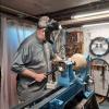
    The last image is supposed to be rotated but the smc software didn't accept it in the correct orientation. A couple of key items: on-off switch, bleed valve, automobile gas filter (all air going into the pump goes through it. I mounted these items on a piece of plywood that I attached to the left end of my lathe. When I'm not using it, it is not in the way.

  2. #17
    Join Date
    May 2010
    Location
    Ambridge, PA
    Posts
    968
    Call Bob Leonard at Frugal Vacuum and see if you can get a copy of his instructions for building your own cups. He shows a couple different way of doing it with different materials. Very helpful. He's a couple pics of my system that's a couple months old. You'll want to get some gasket material from Hobby Lobby type places.

    frugal1.jpgfrugal2.jpgfrugal3.jpgfrugal4.jpgfrugal5.jpg
    Member Turners Anonymous Pittsburgh, PA

  3. #18
    Join Date
    Sep 2015
    Location
    San Diego, Ca
    Posts
    1,647
    BTW, on my early model G0766, I found that the 10 mm (0.394") hole through the spindle didn't allow a 3/8 (0.375") tube to go through easily. The should probably have used something like a "gun drill". The mfr. apparently drilled from both ends and they didn't "quite" meet perfectly in the middle. So, I ended up using a file or drill or something (I don't recall) to help ease the transition in the middle. Now it works fine. There doesn't seem to be any issue of the poly tubing getting stuck or abrading. But perhaps in 50 or 100 years I may want to replace the 25 cent piece of tubing with another one.

  4. #19
    Join Date
    Feb 2015
    Location
    North Jersey
    Posts
    132
    I'm just following up with a resolution of the vacuum system for my Grizzly G0766. Maybe it will help someone in the future.

    This picture shows, from left to right,
    The tubing coming from the pump, which is about 10 feet away.
    The remote on/off switch for the pump.
    The filter.
    The pressure relief valve (not sure that's what it's called).
    The vacuum gauge, with black hose going to the lathe.
    vacuum2.jpg

    This picture shows the black tubing connected to a bearing, inserted into a hardwood receiver that was turned to fit into the hand wheel. I glued foam to the bottom and to the sides to make it airtight. It is removable from the hand wheel, but is held very firmly in use.
    vacuum1.jpg

    This picture shows some chucks that I made using PVC, these Grizzly inserts (which are a bargain), and some foam. The foam works, but I'm not totally satisfied with it - I'm not sure how long the foam will last before it starts coming apart.
    vacuum3.jpg

    I'm getting a vacuum reading of about 21-22 before the chuck. When I put the chuck on, I get a reading of about 19. Not sure I should worry about that. I may try putting some epoxy in all the possible places where there is leakage in the chuck and see how that goes.

    I appreciate all the help from everyone!

    David

  5. #20
    Join Date
    Sep 2015
    Location
    San Diego, Ca
    Posts
    1,647
    David, it looks like you've figured things out pretty well.

    For the leakage at the chuck (minor), have you tried putting on several wraps of teflon tape?

    Looking at the picture of your bleed valve, it seems like it is "downstream" of your air filter. Perhaps I am mistaken. Ideally, you'd want the all of the air going through the vacuum pump, including those times when the bleed valve is open or partially open, to be filtered.

  6. #21
    Join Date
    Feb 2015
    Location
    North Jersey
    Posts
    132
    Quote Originally Posted by Brice Rogers View Post
    David, it looks like you've figured things out pretty well.

    For the leakage at the chuck (minor), have you tried putting on several wraps of teflon tape?

    Looking at the picture of your bleed valve, it seems like it is "downstream" of your air filter. Perhaps I am mistaken. Ideally, you'd want the all of the air going through the vacuum pump, including those times when the bleed valve is open or partially open, to be filtered.
    Are you suggesting that I put teflon tape on the spindle threads when I use the vacuum?

    It seems to me that the bleed valve is in the right place. Air being sucked through the bleed valve goes through the filter on the way to the pump.

  7. #22
    Join Date
    Sep 2015
    Location
    San Diego, Ca
    Posts
    1,647
    David, it looks like you are attaching your vacuum port at the handwheel? If that is correct, you are drawing a vacuum through the spindle and the connection between the spindle and the chuck could leak a little.

    I couldn't tell from the photo what tubes were what. But if the air through the bleed valve goes through the filter on the way to the pump, then you did it correctly.

Posting Permissions

  • You may not post new threads
  • You may not post replies
  • You may not post attachments
  • You may not edit your posts
  •