Results 1 to 10 of 10

Thread: Project: Glass Mosaic Table Substrate (round...)

  1. #1
    Join Date
    Mar 2003
    Location
    SE PA - Central Bucks County
    Posts
    65,850

    Project: Glass Mosaic Table Substrate (round...)

    I recently got an inquiry from a prospective client who in his new-found retirement is going to make an Italian glass tile mosaic coffee table for their home. He's not a woodworker so was looking for a resource to make the base. The mosaic will be 42" diameter and the design he chose is lovely. (I don't have a photo of that to show, unfortunately) We agreed on a BB ply base with a walnut rim, total nominal thickness is 1" and the rim width is about 2" total with 1.5" exposed on top. The plywood is about 4mm below the top of the rim to accommodate the tile and grout. As the size of the project allowed it, other than lumber prep and creating the rim segments, the machining was done on my CNC, 'cause it was the right tool in my shop for the job, honestly.

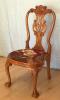
    I will state up-front that I made some errors constructing the staved rim that required an extra step to rectify, but the end result, shown here to start the build looks great. Oh, the customer will be finishing this himself.

    IMG_E8943.jpg

    The design work for the segmentation and circle cutting was thus:

    IMG_E8896.jpg

    The start of any actual woodworking begins with a tree. Well, a piece of one, at least. This is a nice 6/4 walnut board about 8' long.

    IMG_E8895.jpg

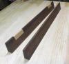
    The board had a little bit of cup and twist, so as always, I broke it down into smaller pieces that made sense and also resulted in less waste. My bench and the CNC machines became sawhorses for this...when in Rome...

    IMG_E8897.jpg IMG_E8898.jpg

    The design in my Aspire software provided the width of the staves necessary to meet the requirements I set forth. But the software only does what one tells it to do. In hindsight, I should have created the staves wider to compensate for any "less than perfect execution" of the circle using this method. Be it known now that there absolutely was "less than perfect execution". But no matter...I did follow the plan at least but the guy who drew it, well...his pay got docked because of extra time on the job to compensate for issues. Here, the width of a bunch of plywood scraps is checked for the plan-identified stave width. These plywood pieces would be used to prove out the angles and lengths also in the design before committing to fifty bucks worth of walnut.

    IMG_E8899.jpg

    I setup the small miter fence on my slider to cut the end angles of the staves. At least I thought I did, conveniently forgetting that it's half the desired angle. This is why we do test cuts with scrap...wink, wink...nod, nod...

    IMG_E8902.jpg IMG_E8904.jpg
    --

    The most expensive tool is the one you buy "cheaply" and often...

  2. #2
    Join Date
    Mar 2003
    Location
    SE PA - Central Bucks County
    Posts
    65,850
    The other key measurement was the length of the inside edge of the staves which was marked from the kerf line on the sacrificial fence. This allowed easy repeatable placement of the workpieces as each would be cut by mitering one end and then flipping them over to cut the opposite end at the same angle, which was 7.5º, BTW, for 24 segments total in the circle. I already had my caliper set to the measurement for some reason, so I used that for the transfer.

    IMG_E8903.jpg

    After cutting a bunch of test segments from the plywood, I moved over to the top of the CNC so I could mark out some things to verify that the test piece was within parameters since there was a funky decimal number involved, I went digital for the last partial inch...it didn't have to be perfect, but it was easier than converting to fractions. I don't know where my mind was here because I normally work in metric now...I guess all that's going on in another situation clouded my thought processes. I'll blame that on the guy who drew the design, too. heh...heh...

    IMG_E8905.jpg

    After stitching together the test segments and laying it on the lines I just created things looked pretty darn good. At least that was what I was convinced of. In reality, I should have done the whole circle as with close tolerances in the final dimension, I would have known that it was a better thing to made the staves wider to start. I had enough space to do that and another half inch or so would perhaps made things a little easier, at the expense of a little more material usage.

    IMG_E8907.jpg

    Convinced that things were on the right track, it was time to get the walnut ripped to width and one of the test pieces was used to repeat the carefully measured with calipers width on the real material.

    IMG_E8909.jpg IMG_E8911.jpg

    One handy thing with the slider is that it's easy to mark the position of something with a sharp pencil...like the angle for the staves...so the short miter bar could be reset after the stock preparation

    IMG_E8910.jpg

    A bunch of cuts later, there were 24+ pieces of walnut ready to create the rim/frame with. The plan was to join using Dominos because of all the end grain and that's what I did. They were centered in what I thought would be the middle. It was clear that they would get "exposed" inside the rebate for the plywood, but that wasn't an issue since any strength lost from that cutting would be made up for when the BB panel was glued into the rebate. Best laid plans, you know...the designer guy mentioned previously wasn't incorrect in the thinking. But the guy doing the cutting and assembly wasn't as accurate as needed to hit the mark. More on that to come.

    Laying out the location for the Dominos...a scrap serves as a consistent marking guide

    IMG_E8913.jpg IMG_E8915.jpg
    Last edited by Jim Becker; 02-01-2021 at 3:08 PM.
    --

    The most expensive tool is the one you buy "cheaply" and often...

  3. #3
    Join Date
    Mar 2003
    Location
    SE PA - Central Bucks County
    Posts
    65,850
    One of the things I love about the Domino system is that it really does make for nice, tight and strong connections between workpieces. As long as you index off the same face (the top in this case) the result is very good. I made a little fixture to hold the workpieces while making a whole lot of oblong holes...like 48+ test pieces worth of them...

    IMG_E8919.jpg IMG_E8916.jpg IMG_E8917.jpg

    The construction was assembled in two halves...that made sense at the time. Because things went together pretty exactly, I only had to clamp to the bench overnight to insure it stayed flat. The better choice would have been to dry fit the whole circle which would have detected the minor imperfection that came into play later and then glue it up as a whole circle. No matter...solving challenges is part of the deal.

    IMG_E8920.jpg

    The halves were adjusted by shaving the angles on the slider so that they would mate together with zero gaps.

    IMG_E8923.jpg

    And then they were glued together, again, clamping to the table to insure flatness. Looks like a perfect circle, right? Not. It was a "hair toward oval". My bad.

    IMG_E8924.jpg

    While the nice walnut circle was enjoying the tates of glue, it was time to cut the BB substrate. The parameters were for a 42" field for the tile mosaic plus about 3/4" to support the rim. When I picked up the sheet of BB, I took advantage of the supplier cutting it to 49" wide to save a step for me as that's the maximum width of my machine. Cutting a circle isn't exciting but with the CNC, it's pretty much exactly the circle you want (or at least what you told it to cut) and it's actually a perfect circle. I can live with that.

    IMG_E8925.jpgIMG_E8926.jpg
    Last edited by Jim Becker; 02-01-2021 at 3:24 PM.
    --

    The most expensive tool is the one you buy "cheaply" and often...

  4. #4
    Join Date
    Mar 2003
    Location
    SE PA - Central Bucks County
    Posts
    65,850
    That was the easiest part of the project right there...making a nice circle. But then again, it's time to make more circles, but on that lovely staved walnut ring. Some crap material was glued to the edges of various staves around the construction so it could be screwed down to the spoilboard for cutting. It was here, during the process of calculating the center that the "ovalness" was detected. It didn't actually have to be perfect, but it was off enough that it made clear that wider staves would have been a better idea. I ran a few test toolpaths with almost no depth and a sharp angle v-bit to see where things would end up. For the inside, a slight and minor adjustment to make the field size a hair larger was needed and made.

    IMG_E8927.jpg

    After a full thickness cut to create the inner edge of the field, the rebate was created to house the plywood circle previously created. A tile was used to help sneak up on the thickness of the inner rim so that when the plywood was installed, the depth of the area where the tiles and grout would go would be pretty much where it needed to be. I did calculate that using the old math thing, but I'm still more comfortable cutting it down close and then shaving off a little more until getting right to the perfect spot. It takes more time, but the end result it worth it.

    IMG_E8928.jpg

    The good news...it fit. So it was glued in and left to sit overnight.

    IMG_E8929.jpg

    The next day, I dropped a few screws through the plywood into the spoilboard so I could forget about using tabs on the outside cutout that would be concentric with the inner circle. It was then time to do that cutout. The good news is that even with the misshapen walnut construction, there was just enough material to get the exact rim width required. The bad news (and resultant bad words and lack of a photo because of that audible distraction) was that things were skewed enough that several of the Dominos became exposed. There was also some tearout I was not happy with. "Chuzbut". Amazon to the rescue...ordered some 1" walnut edge banding and had it in two days. I had something else to do those days anyway.

    While I have a small edgebander, I just didn't feel like creating a fixture to hold up and spin this big table to apply the banding and also felt I'd be getting involved in a lot of tape work to insure it went on tight. I was correct in that latter case. In other good news, I didn't destroy our household iron, either.

    IMG_E8938.jpg IMG_E8940.jpg

    This particular edge banding was very nicely cut and I was able to do a nice angled cut for the joint through two layers, tape it and iron it fast. This was kinda like binding a guitar body, but on a larger scale and not involving CA glue or acetone. After sanding, I honestly had to look for a long time to even find the joint.

    IMG_E8939.jpg IMG_E8944.jpg

    Well, alrighty now...the edges were specified to have a very slight roundover and while I originally intended to do that with a router, with the edge banding, that was out of the question for the risk of tearing/splintering. So sanding it was with the ROS and by hand. It really does look good and once the client gets finish on it (I'm recommending he use an oil based wipe on for both color and ease) it's going to really look great. There's a little bit of curl in that walnut, too. If the client graces me with a photo of the completed table with the mosaic, I'll add it to this thread at that time.

    So I learned a few lessons on this one and aside from the imperfections in measuring, etc., the larger one was to be more generous with the initial material for a rim like this.

    IMG_E8943.jpg
    Last edited by Jim Becker; 02-01-2021 at 4:02 PM.
    --

    The most expensive tool is the one you buy "cheaply" and often...

  5. #5
    Join Date
    Nov 2013
    Location
    Crozet, VA
    Posts
    648
    Sweet recovery with the edge banding, and nice look overall. I feel like the ability recover from the inevitable “oopsies” is what becoming an experienced woodworking is all about.
    There is a very fine line between “hobby” and “mental illness.” - Dave Barry

  6. #6
    Join Date
    Jan 2004
    Location
    Lewiston, Idaho
    Posts
    28,532
    Nicely done Jim!

    The lessons we learn as we gain experience often can be the most interesting part of the journey in woodworking IMO.
    Ken

    So much to learn, so little time.....

  7. #7
    Join Date
    Apr 2017
    Location
    Clarks Summit PA
    Posts
    1,744
    Great foundation Jim! Can you try to gets pics of finished table?

  8. #8
    Join Date
    Mar 2003
    Location
    SE PA - Central Bucks County
    Posts
    65,850
    Quote Originally Posted by Mark Rainey View Post
    Great foundation Jim! Can you try to gets pics of finished table?
    Yes, I'll request that from the client.

    -----
    Thanks for the nice comments folks. I find it important to not just post about the great result, but also to clearly define things that didn't go well. That reinforce the lesson on myself but might also help someone else avoid the same. And for the benefit of newbies, I think it's important to be honest that even someone who's been playing with this stuff for decades is not immune from being human as well as we all learn from taking on something new and challenging. This was the first time I've done this kind of project. I'll certainly enjoy the money it brought but the lessons were more valuable than that for sure.
    Last edited by Jim Becker; 02-02-2021 at 9:28 AM.
    --

    The most expensive tool is the one you buy "cheaply" and often...

  9. #9
    Join Date
    Mar 2005
    Location
    Philly, PA
    Posts
    168
    Jim, don't be too hard on your assembly and design guys. This "woodworking" project might be better called a math problem - calculus anyone? In any case, thanks for sharing both the problem, the solution, and the positive attitude. Definitely a lesson for all of us.

  10. #10
    Join Date
    Mar 2015
    Location
    SE Michigan
    Posts
    3,225
    Nicely done, Jim. I’m sure the client is very pleased. I must admit reading through the build, it made my head hurt! That’s a lot of figuring! Kudos to you. Look forward to seeing the finished piece.

Posting Permissions

  • You may not post new threads
  • You may not post replies
  • You may not post attachments
  • You may not edit your posts
  •