Page 1 of 3 123 LastLast
Results 1 to 15 of 45

Thread: Underbench cabinet

  1. #1
    Join Date
    Feb 2004
    Location
    Perth, Australia
    Posts
    9,489

    Underbench cabinet

    A few requested that I post the build of the underbench cabinet I am building. I hesitated to do so since this is a blended build; however it is really mostly hand tools, and I have reached the point where it is almost all hand tools.

    I find it interesting that when I post on the power tool forum, part of my aim is to encourage power tool users to explore hand tools. Now, on the hand tool forum, I want to encourage those here to make proper use of power and machines. There are no bogey men here, just tools.

    This build is also on my website: http://www.inthewoodshop.com/Furniture/index.html

    I decided to add a cabinet to my work bench. There are just too many tools on the wall, and many would be better off stored in drawers where I can reach for them when needed.


    The cabinet will span as wide and high as it can go without being impeded by either hold downs or the sliding deadman.

    The cabinet is deep - too deep for drawers. The plan is that the drawers will not be full length deep internally, but have full length sides through to the rear to create a full extension when siding out. Internally, it has been my plan to use siding trays within the drawers ... fewer drawers externally, but more drawer space internally.

    This tool cabinet is inspired by the North Bennet Street School version (a well-known woodworking school in Boston). The tool cabinet is one of their training pieces. One became an article by Tommy MacDonald in PW magazine.

    Tommy's tool cabinet ..


    Mine will be a little larger, more drawers, and a more complex construction involving mitred through dovetails ...


    Dimensions: 660mm x 400mm x 400mm (26" x 15 3/4" x 15 3/4").

    Small drawers: 205mm x 70mm (8" x 2 3/4")
    Large drawers: 305mm x 95" (12" x 3 3/4")


    Merbau is definitely going to add some weight to the bench! The case being dovetailed.


    Well, this is about the fourth mitred through dovetail case I've built in about 18 months. I must be getting the hang of it now, since this was straight off the saw. No tweaking needed. Merbau is hard and has no give at all ...


    The Merbau comes as a panel from Bunnings, a local hardware store. This is shop furniture and I make no excuses for taking a shortcut. The 18mm thick panels are flat and ready to go. Literally all I have done is cut them to size.


    The penalty is that the wood is bloody hard!

    The drawer fronts will be Jarrah. I intend staining the Merbau case to match the drawer fronts.

    Just to prove to myself that it was no fluke, it happened again ...


    I continued on until all four sides were dovetailed. Through dovetails with mitres at each corner. And every one went together off the saw ... well, almost - one mitre required a smidgeon of a mm pared away to close tightly. All tight and square. I am quite chuffed.


    The difficult part is to get the mitres to close along with the sockets ...


    Inside the bench ...


    Regards from Perth

    Derek


  2. #2
    Join Date
    Feb 2004
    Location
    Perth, Australia
    Posts
    9,489
    Ripping with the slider

    Time to use the slider. THIS is what the parallel guide on the slider can do. It is like a Fritz & Franz jig on steroids ...


    With the case done, the next step is to prepare the boards for the drawer blades/frames. I have found a chunk of Jarrah, about 50mm thick and 180mm wide and about 950mm long. This needs to be sliced up into 50mm wide boards … which will be further reduced to 12mm thick drawer blades.


    Place the board against the parallel guide ...


    ... and rip one side to 50mm ...


    Now rip the second length ...


    .. and the third. How safe is a slider? This is where one stands - well away from any possible kickback (which does not occur on a slider, anyway. And the hands are no where near the blade ...

    The importance of the clamps - how else does one hold a wide, thick and heavy board just 50mm from the parallel guide?


    How good are the saw cuts? Good enough to joint with, and not require a jointer for the edges.


    Here is the board ...


    Close up ...


    But ...


    Question: How do you register the fixture for parallel to the blade upon installing it on the sliding table? It appears the fixture is secured to the table by means of the two recessed bolts presumably connected to nuts captured in the T slot of the K3 table extrusion, which is very secure but normally allows slop side to side. Are there fixed registration blocks on the underside that fit the slot precisely? Or do you do register the business edge of the fixture against a known parallel, like the rip fence, then tighten down? ...Very nice design, BTW--the most appealing and practical I have seen. I particularly like how you integrate the clamping function (using the sliding table this way with unclamped workpieces always felt more than a little unsafe to me and trying to clamp from the ends can be a hassle) and how it lends itself to being a taper jig. Also great that it can live on the saw without crippling the crosscut function (David Stone)


    Hi David

    It is really simple, and quick.

    The fixture (for details, see
    here) is bolted to the slider table or wagon via the T-slot, as you noted. The holes for the bolt are a smidgeon oversize - enough for wiggle room to align the side of the fixture with a saw tooth (at the front) and the zero clearance on the crosscut fence (at the rear).

    The side of the fixture (facing the blade) is always a zero clearance. Place the rough and skew edge of a wide rough sawn board against this and rip it straight.

    The parallel guide is set from two T-tracks, each with an identical metric scale. (These scales are set into a dado, attached with screws, each of which has a little adjustability to fine tune perfect accuracy).

    The idea that this would be a better fixture for tapering came when I made this simple aid several months ago to taper legs for a table. Clearly, this was quite rudimentary, and a fence would have made set up (for the other legs) so much easier ...


    Regards from Perth


    Derek


  3. #3
    Join Date
    Feb 2004
    Location
    Perth, Australia
    Posts
    9,489
    The Rebate

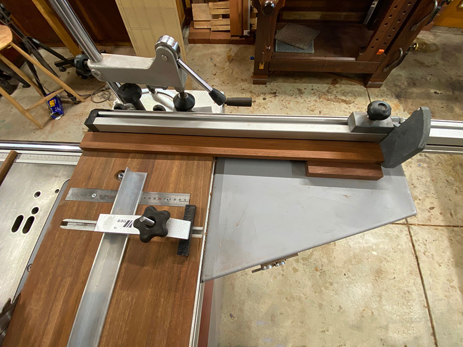
    A rebate can be made with a handheld router, router table, table saw, a handsaw and chisel, and a hand plane such as a moving fillister. My preference is the latter.

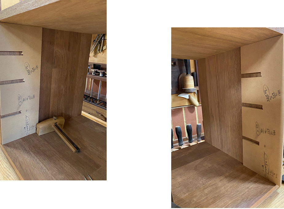
    What can be more simple than a fillister plane along an edge? Well, the plane needs to be set up, especially when planing interlocked grain, as we have here. And before this can take place, the case needs to be prepared if the desired result is an accurate - flush and square - rebate.

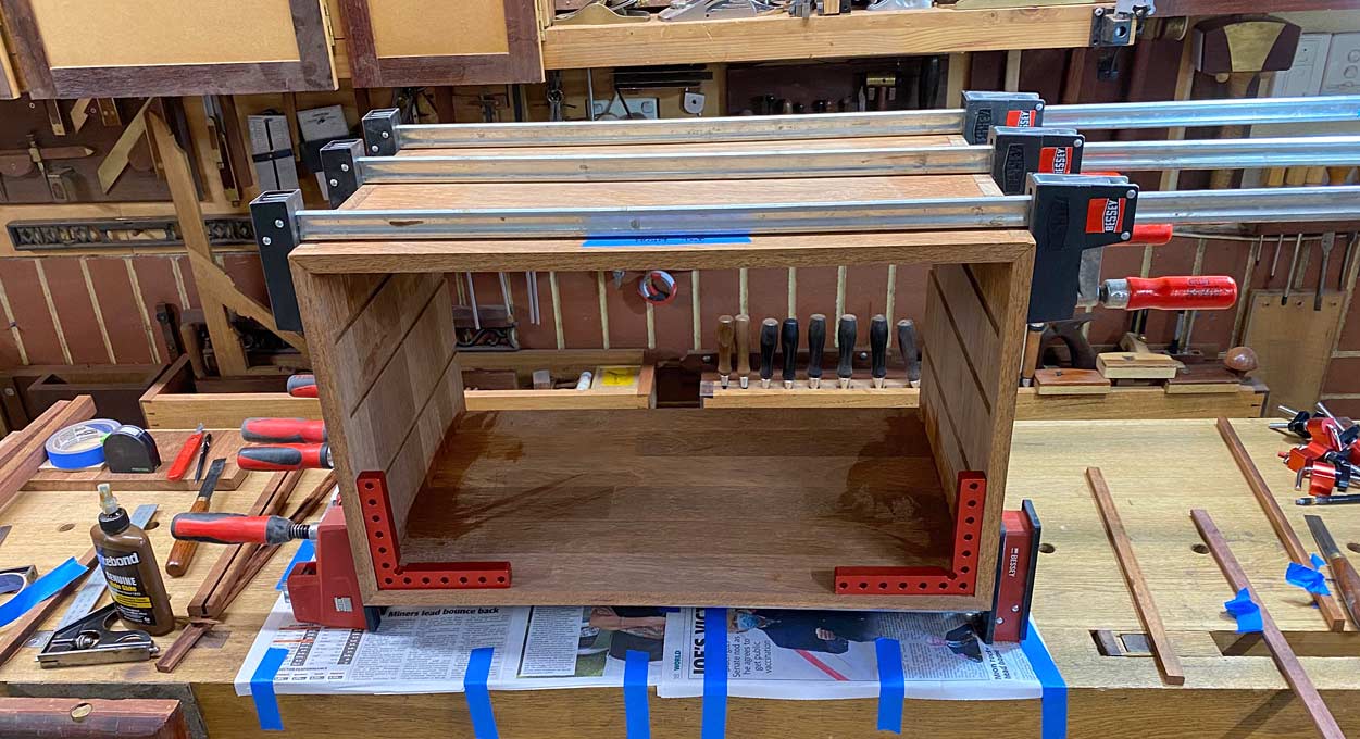
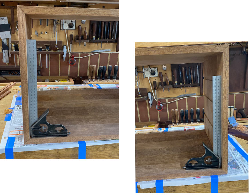
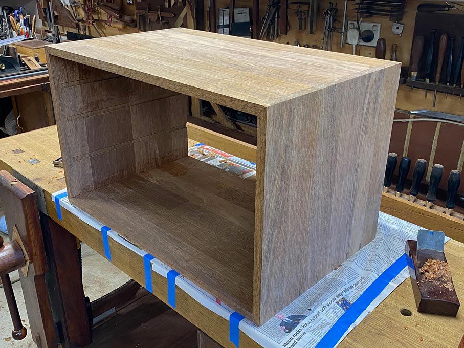
    The first step is to level and square the front and back edges of the case. My plane of choice here is a small bevel up plane with a high cutting angle. It is low like a block plane for easy handling, which is helpful when the case is high on the bench ...


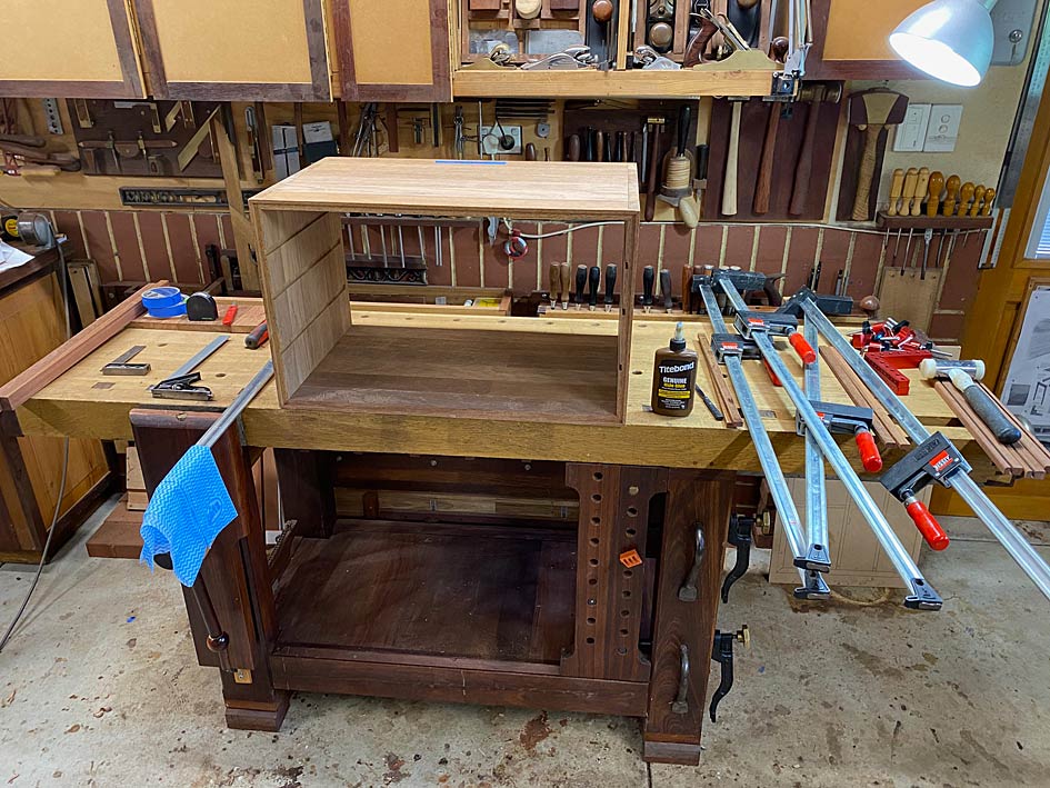
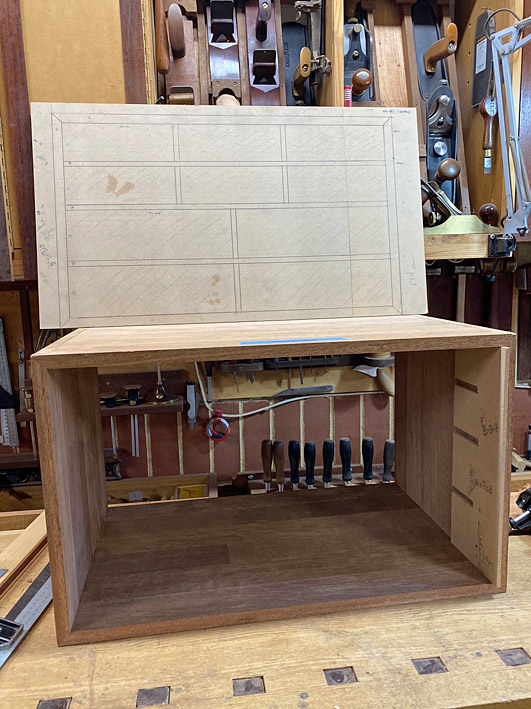
    The case is 18mm (3/4") thick. The rebate will be 7mm deep x 12mm wide. This will allow for a 6mm thick rear panel.

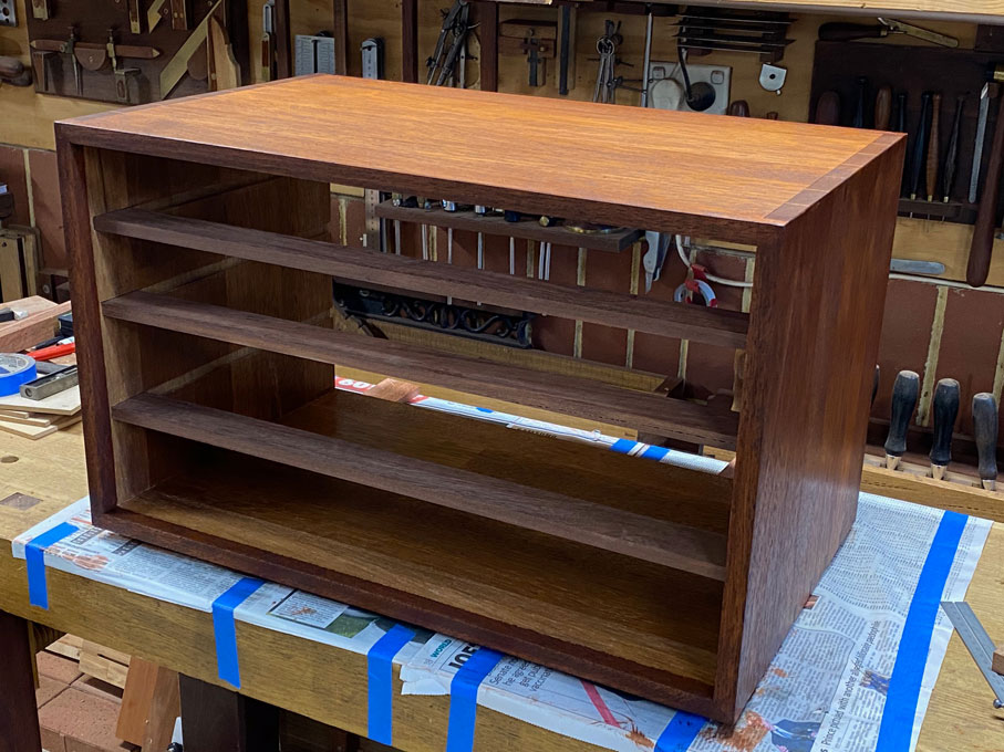
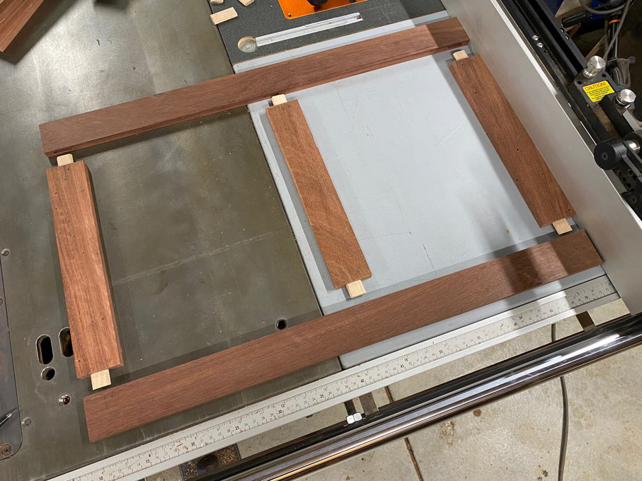
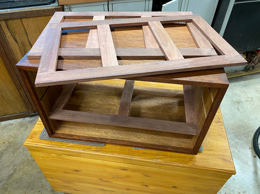
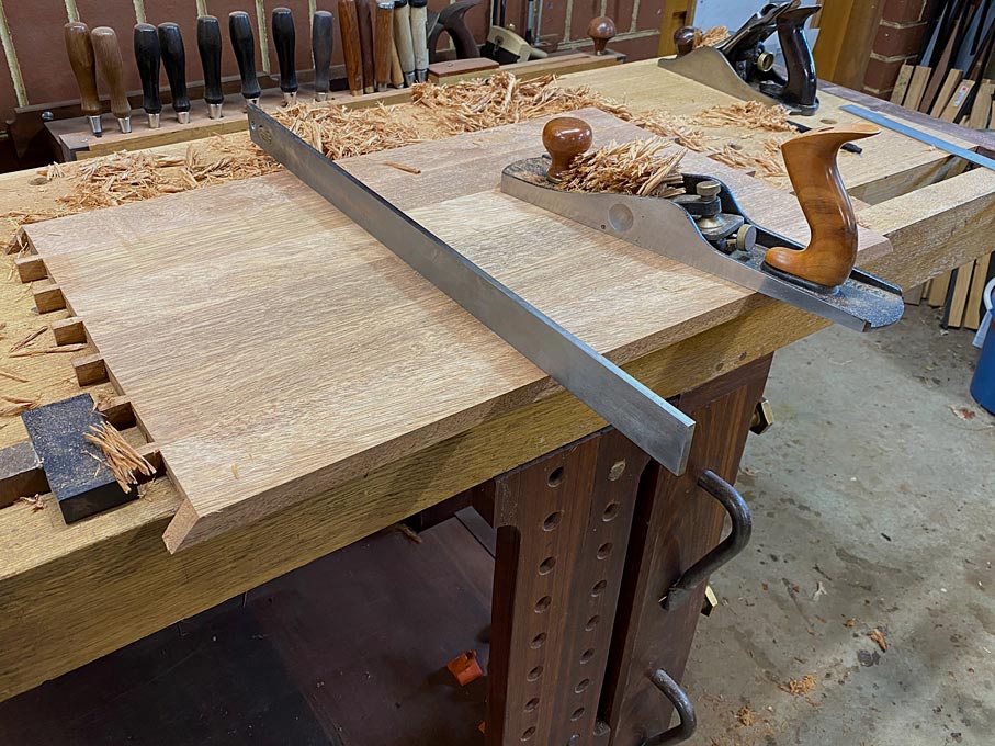
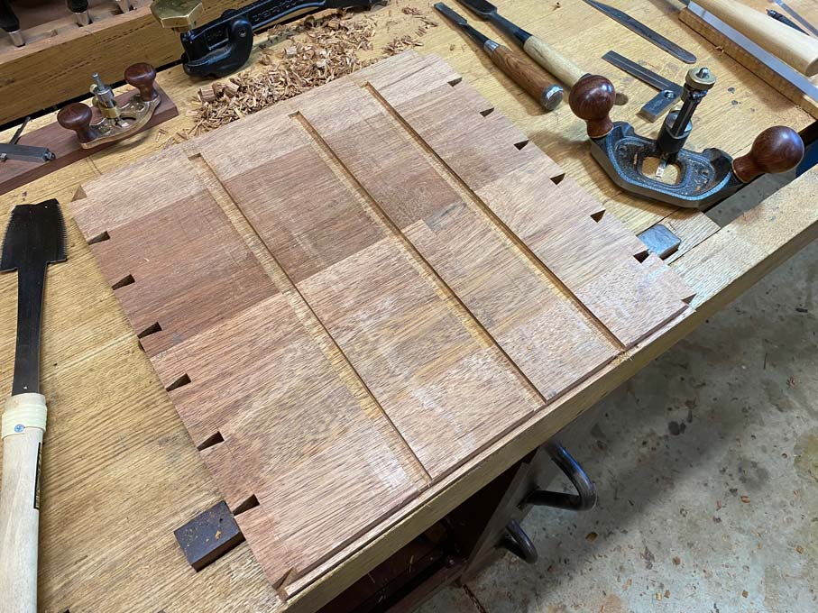
    The cabinet will have four rows of drawers, with the lowermost row running on the bottom of the case. It is important that this surface is perfectly flat in order that the drawers run smoothly. The boards making up the sides were flat out of the packaging. Certainly flat enough for a case, but not quite flat enough for drawers to run on with the level of precision desired here. They need further work ...

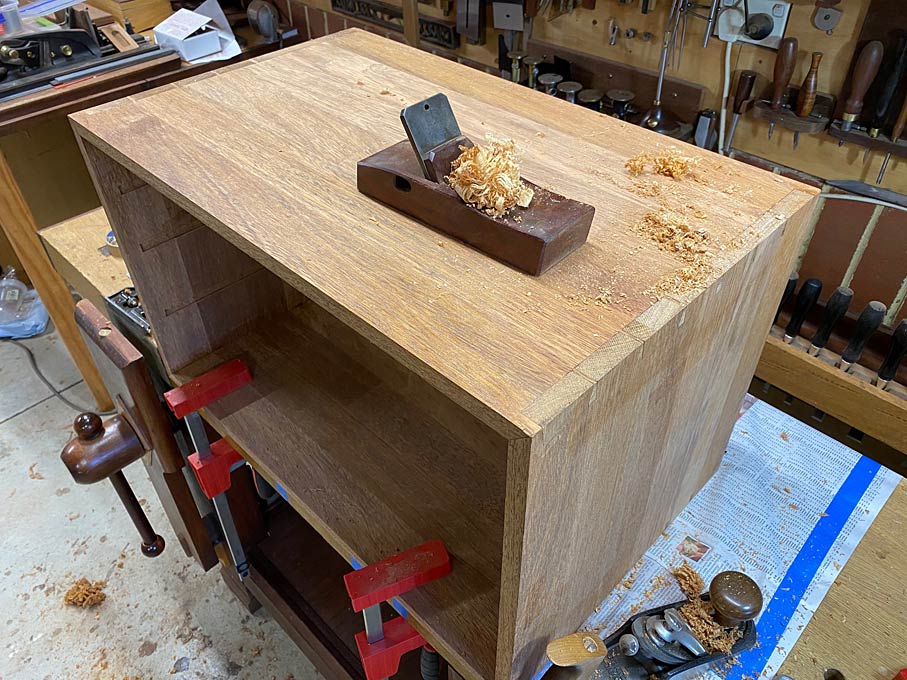
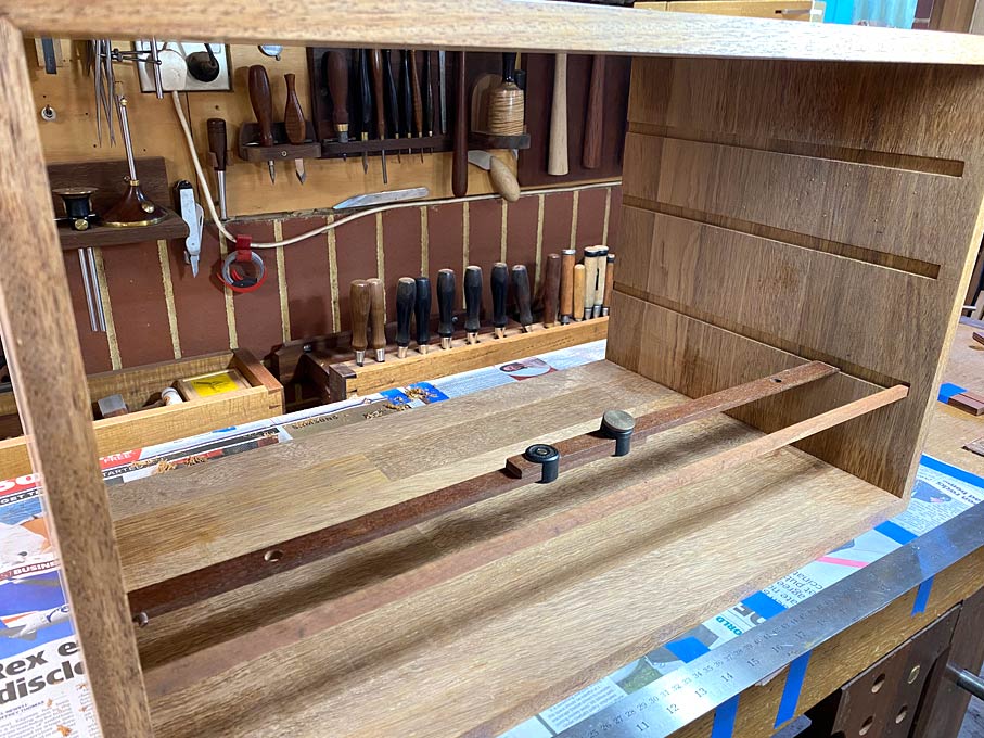
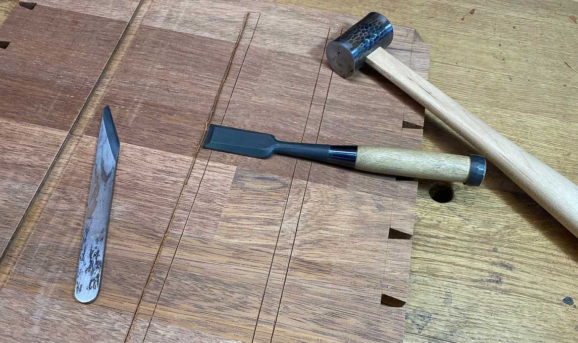
    The case is pulled apart, and the lower panel is traversed. Note that the surface is first covered in pencil scribble to monitor where the high- and low points are ...


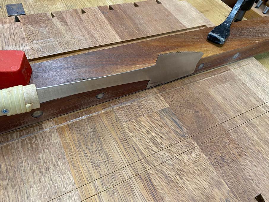
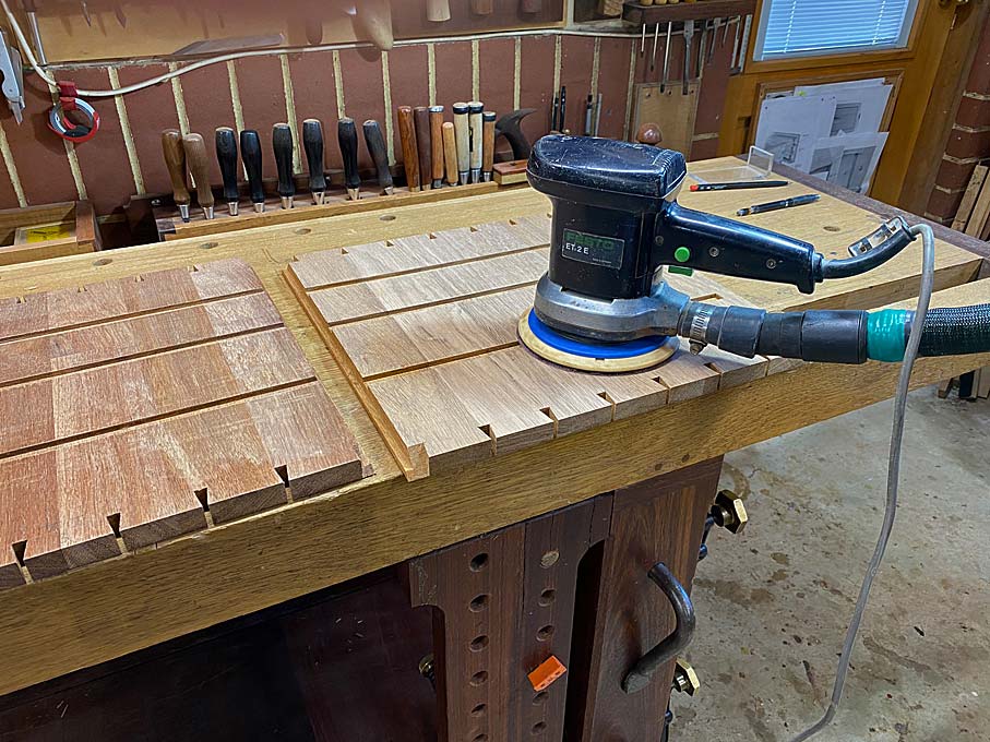
    A straight edge and a longer plane are used here ...


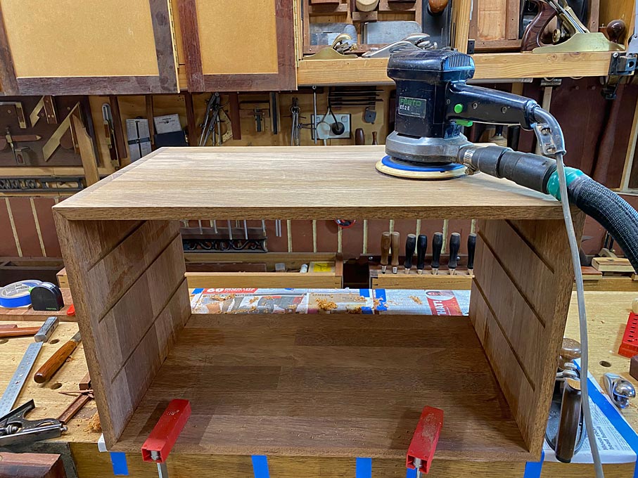
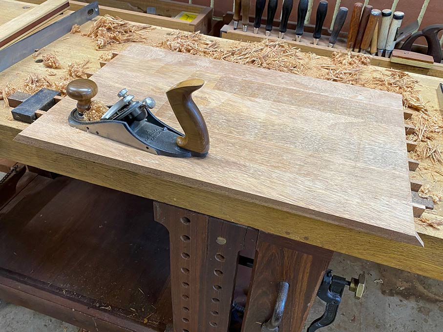
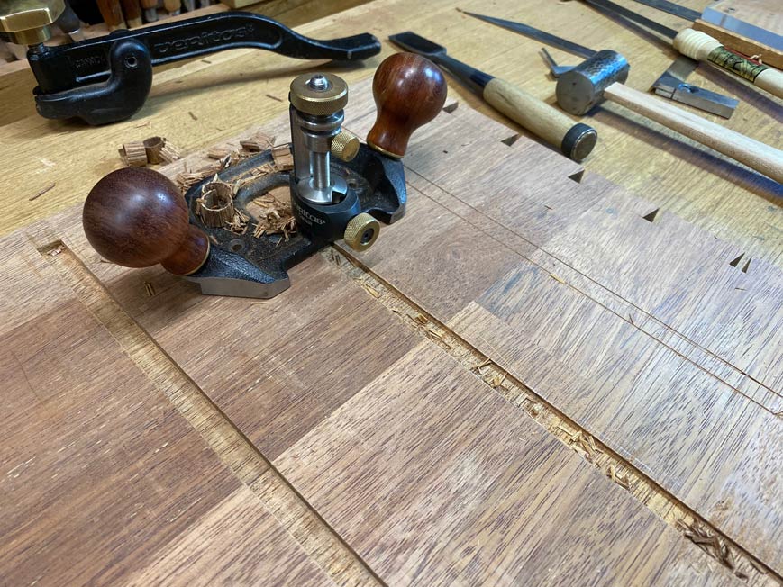
    The blade here is slightly cambered to avoid leaving track lines. A very light surfacing is completed with a smoother, more to remove any fuzz than to level ...


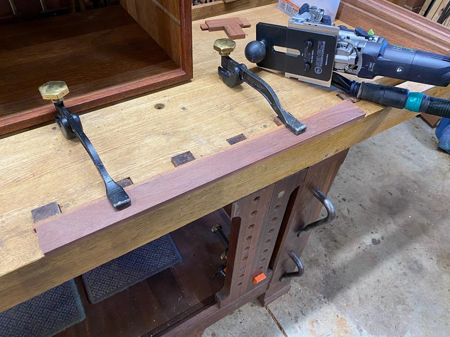
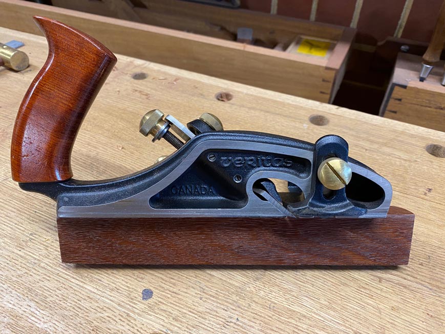
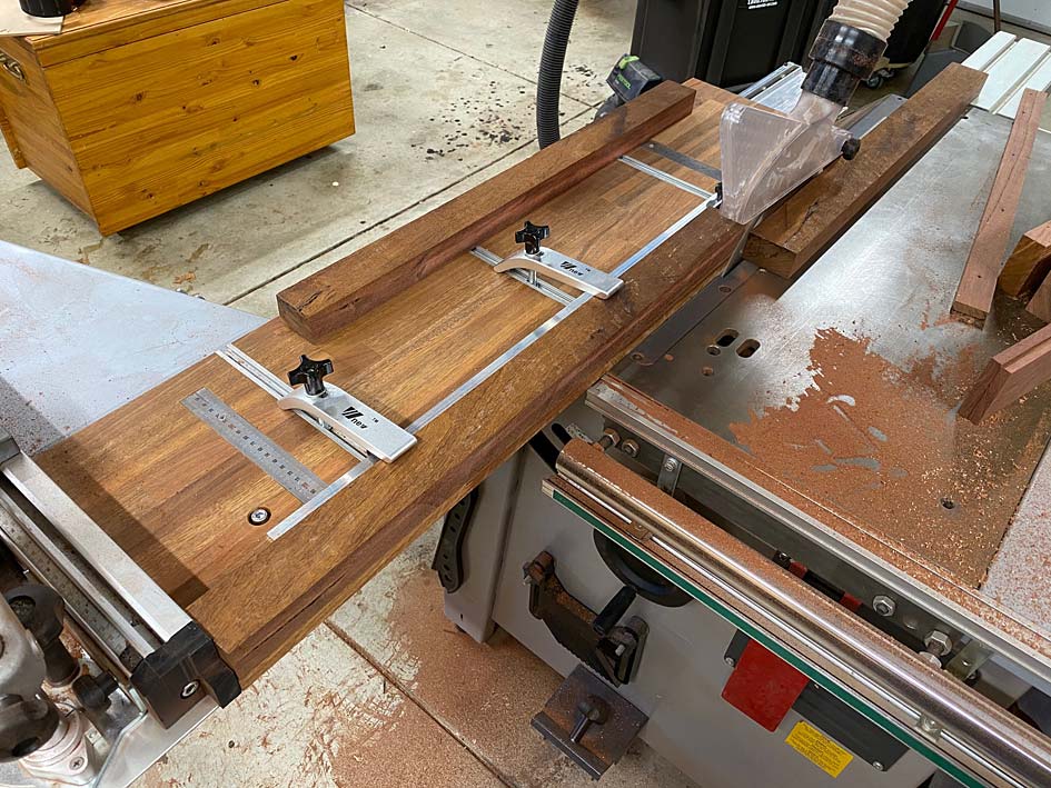
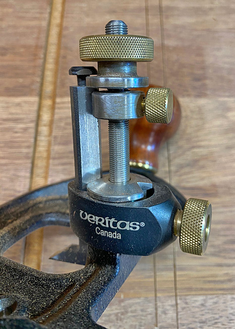
    The moving fillister of choice is the Veritas Skew Rabbet Plane ...


    Those familiar with this plane will note that the front knob has been removed. My preference is to rest my thumb on that spot and apply downforce, while the palm applies force against the side of the plane. Here is an example from another build ...


    This fillister has a deeper subfence. The depth stop knob has also been slotted for ensure that it has been tightened securely ...


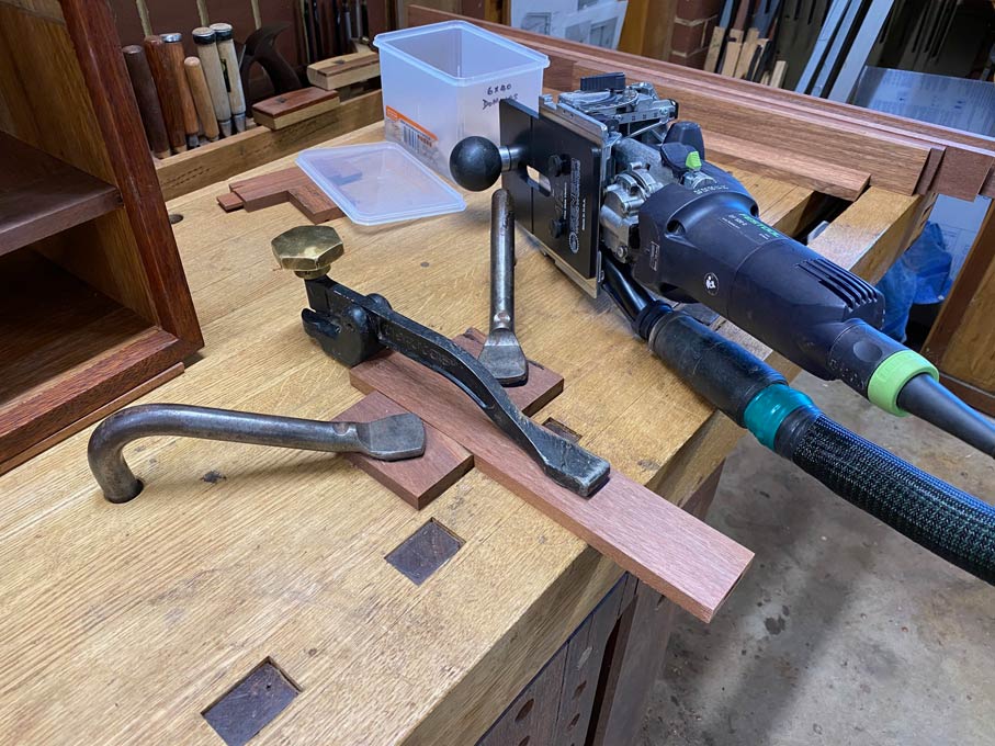
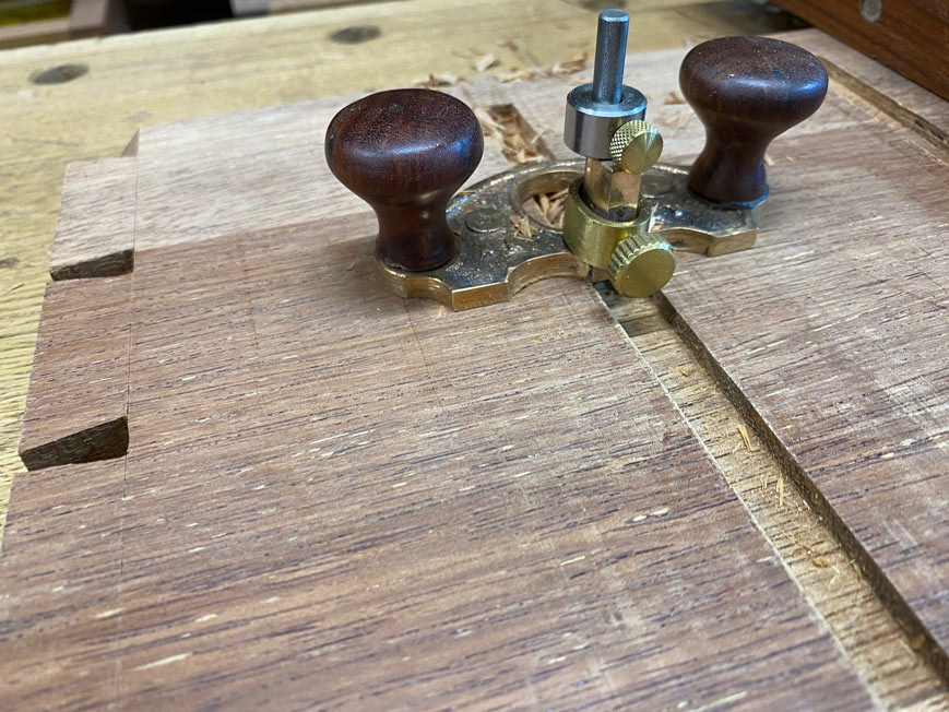
    The plane is generally only set up to slice with the knicker ahead of the blade when planing across the grain. However, the Merbau used here has especially interlocked grain, and the nicker it employed to prevent spelching on the shoulders.


    Here, the nicker is a smidgeon outside the body of the plane. The skewed blade lies in-line with the nicker. This has another purpose, which is to cut into the lower corner of the rebate and keep it clean and square. Otherwise it would allow waste to build there, and the inside would create a slope.

    In addition to the line created by the nicker, a cutting gauge is run along the rebate boundary. This may be used after or during the rebate is cut to clean out the inside corner.

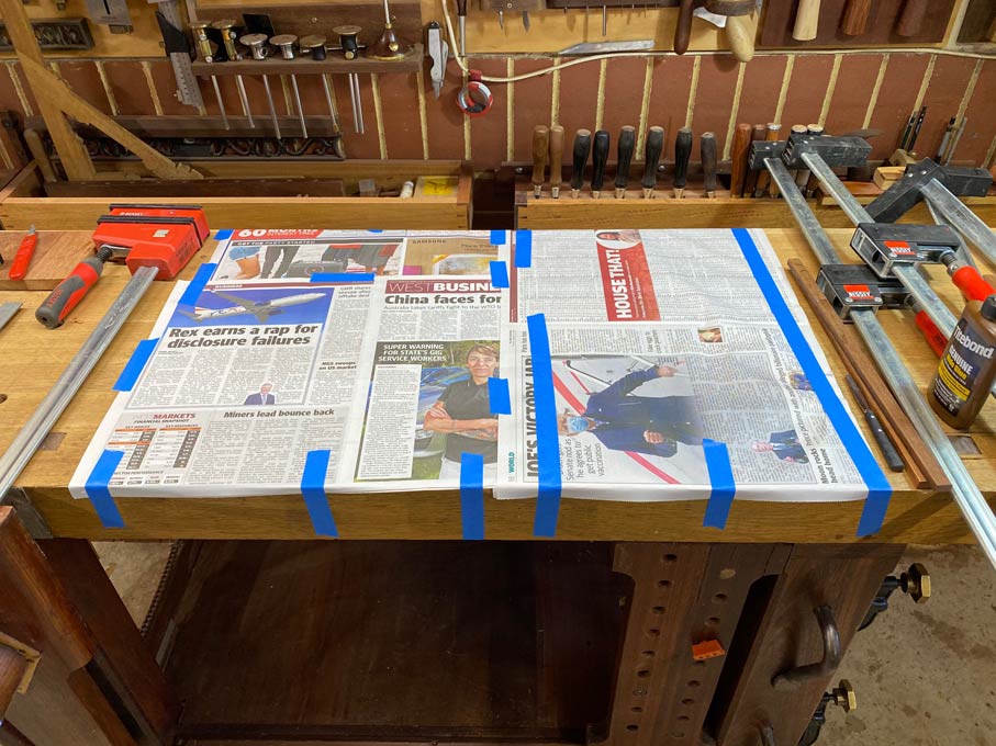
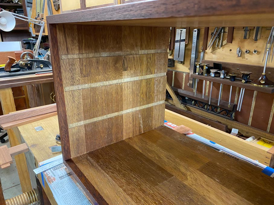
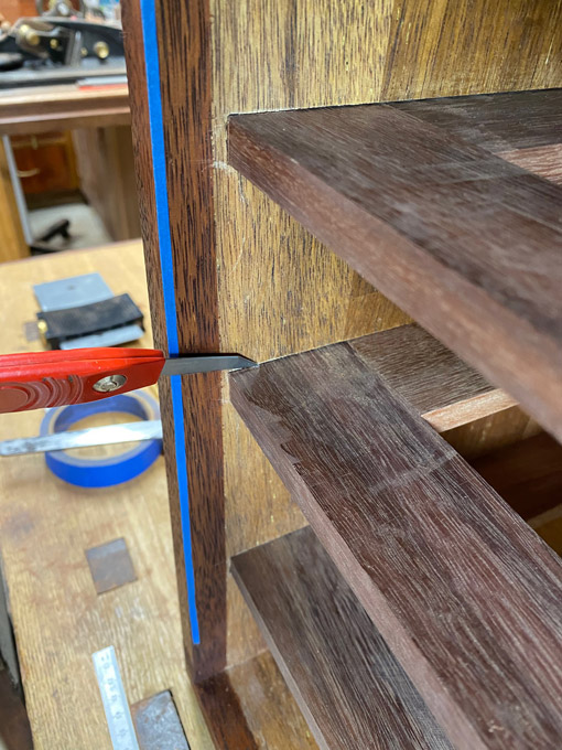
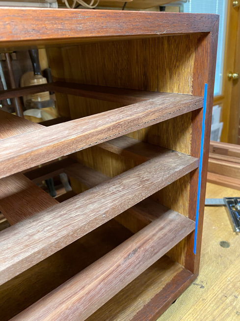
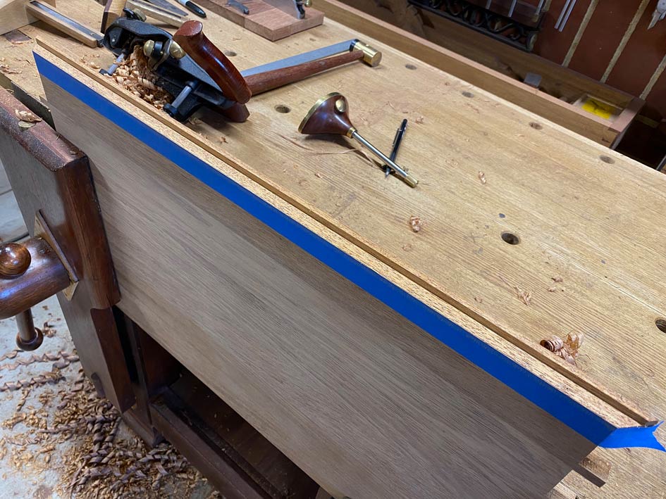
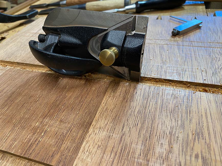
    One last item of preparation is, following marking out the rebate (again with a cutting gauge), the lower boundary line is highlighted with blue painter's tape. This is simply to aid in monitoring the plane as it gets close to the line.

    This is what the shavings from fairly straight-grained wood looks like ...


    This is the result when the grain is significantly interlocked ...


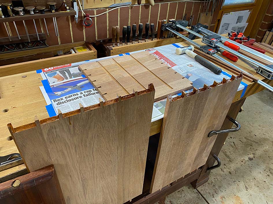
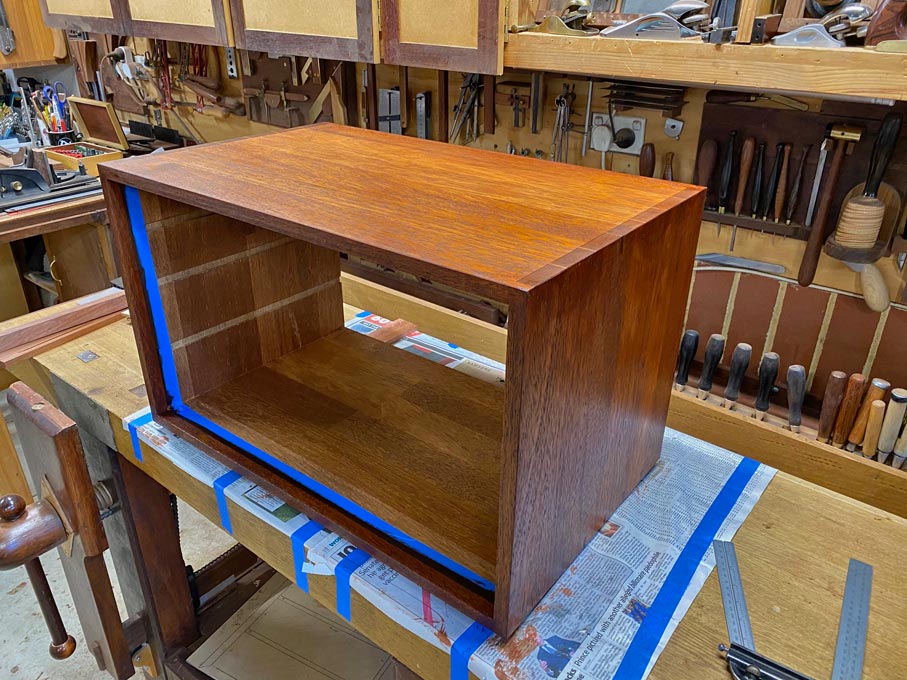
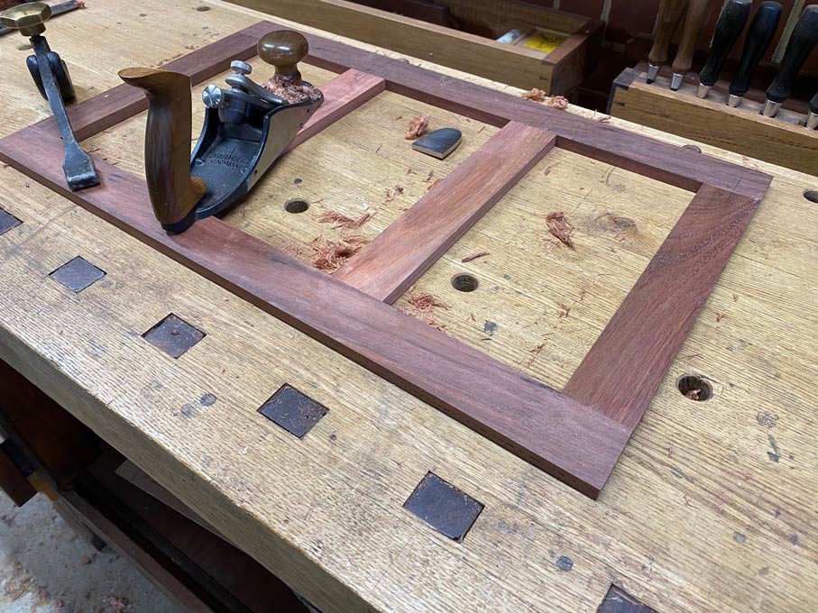
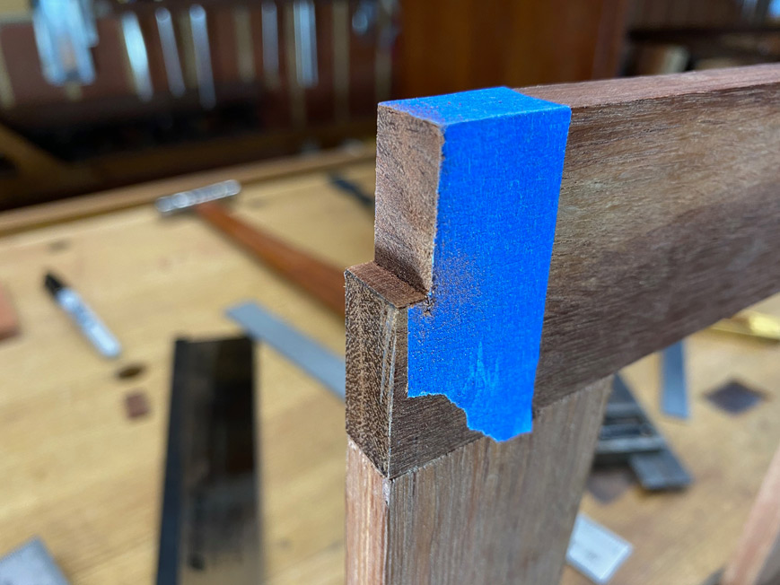
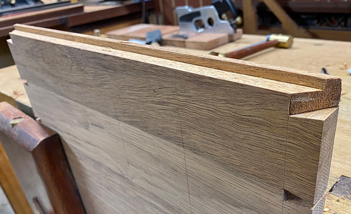
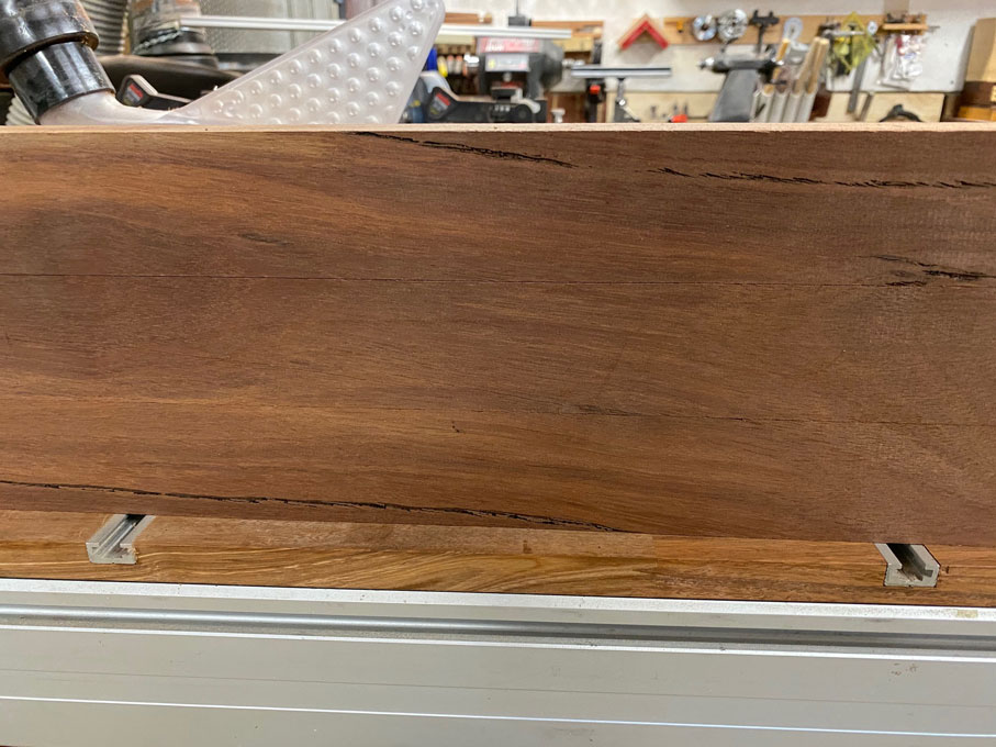
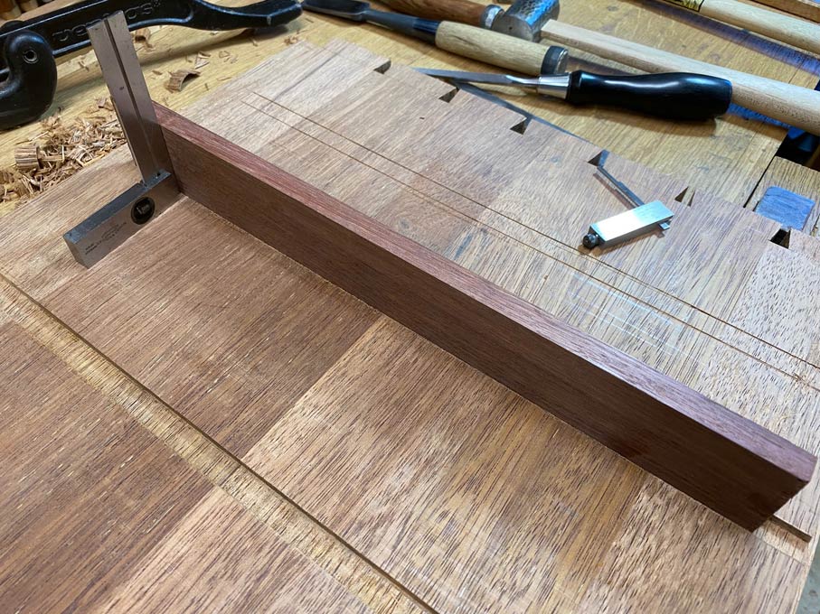
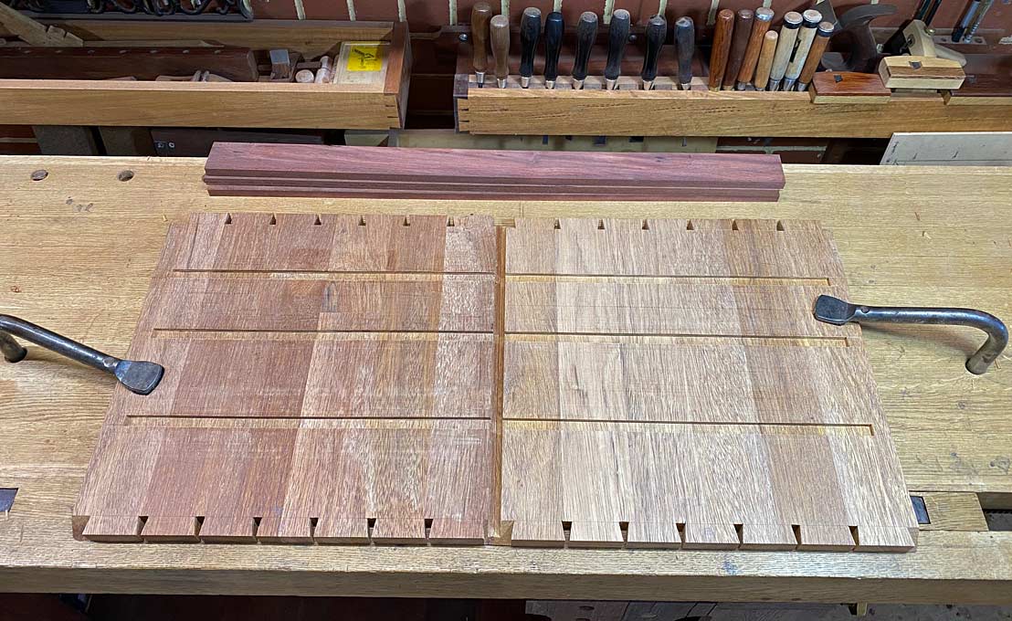
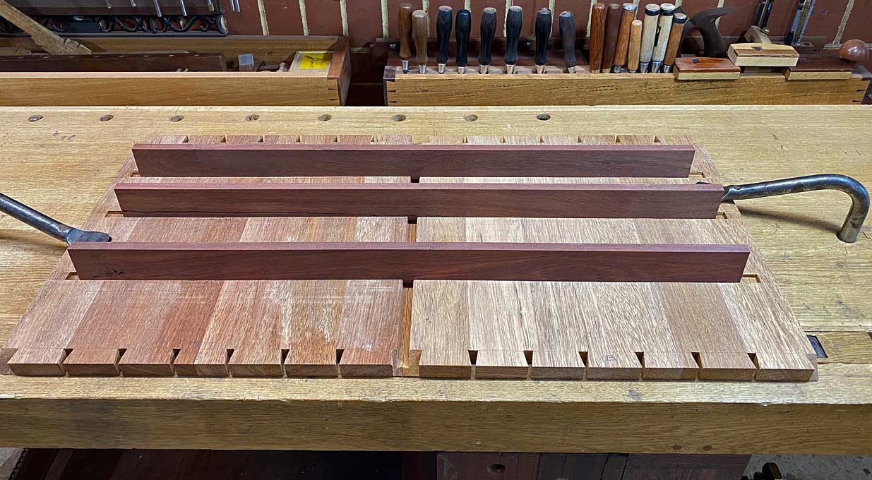
    The case is dovetailed with mitres at each corner. There are two benefits for this: the first is aesthetic; the second is that it permits the panels to be rebated through the full length (otherwise stopped rebates are needed) ...


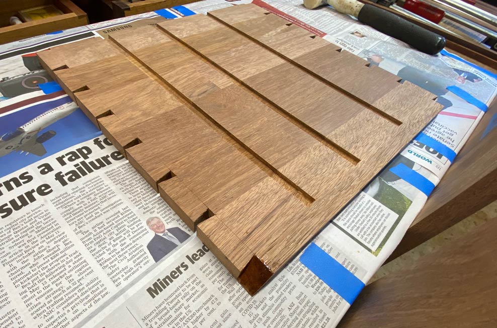
    Here is a better glimpse of the grain direction ...


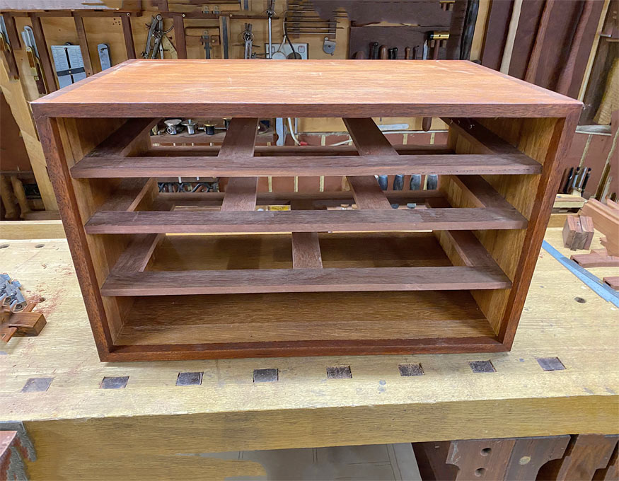
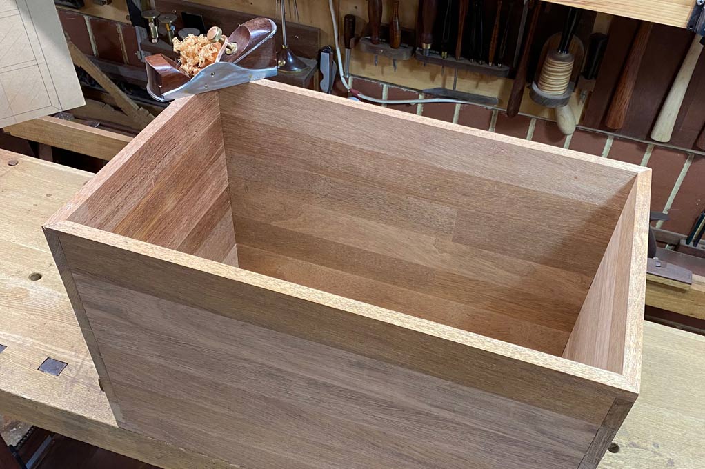
    The case back is done ...


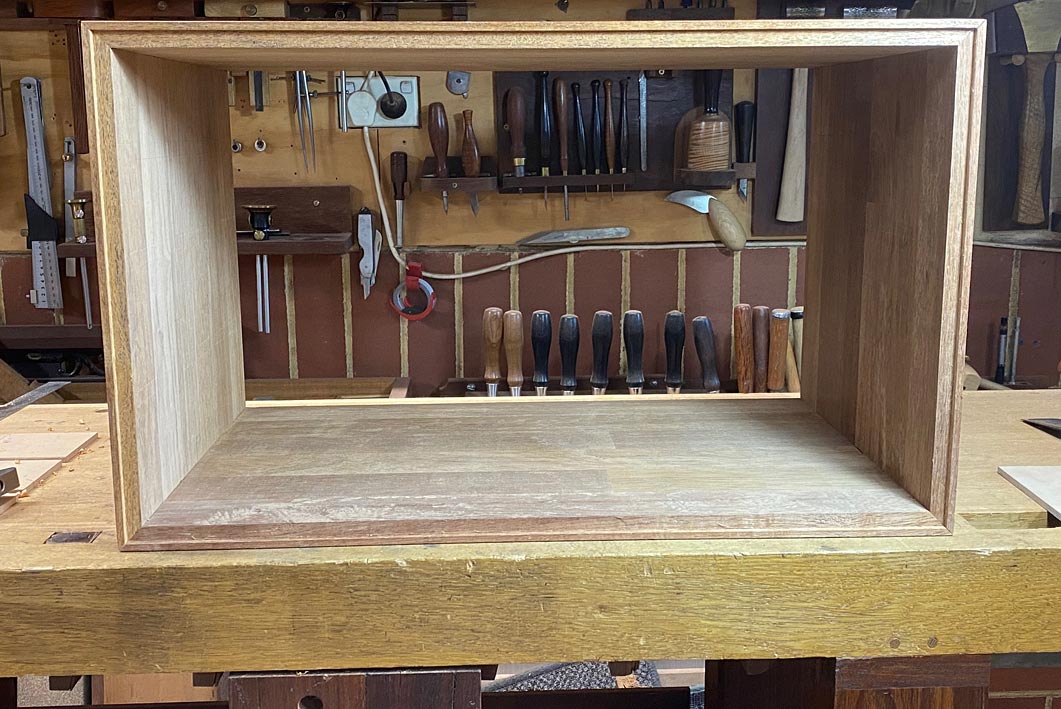
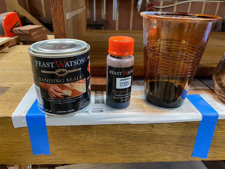
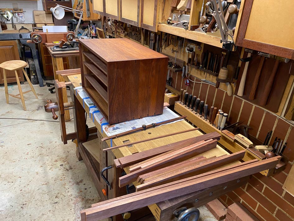
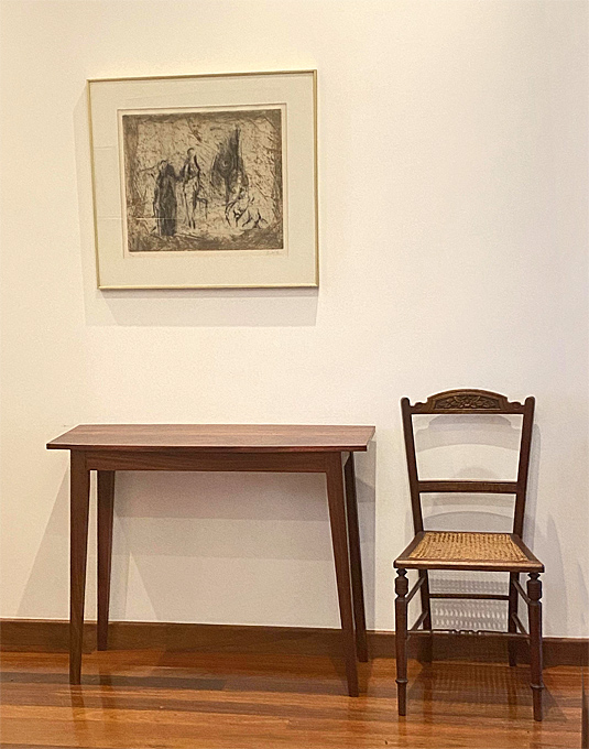
    The finish we were looking for ...


    Regards from Perth

    Derek

  4. #4
    Join Date
    Sep 2008
    Location
    N. Idaho
    Posts
    1,621
    Derek,

    Looks great and happy to see that I'm a bit ahead still on my chest, since I started mine almost 3 years ago...

    The ripping jig is slick and I'll file away for when I have a chance to upgrade to a slider in the next couple of years. One thought would be to see about buying parts from Incra for indexing each end. Specifically, the transverse grooved tracks used on their miter gauges could be inset into a jig and used like the larger Incra jigs and fences without having to buy the whole kit, no? And without squinting at a measuring tape twice. Or maybe setting both ends is straightforward and it wouldn't be worth the effort?

    Thanks for posting and will look forward to seeing progress.

    Best,
    Chris
    "You can observe a lot just by watching."
    --Yogi Berra

  5. #5
    Join Date
    Feb 2004
    Location
    Perth, Australia
    Posts
    9,489
    Quote Originally Posted by Christopher Charles View Post
    ...

    The ripping jig is slick and I'll file away for when I have a chance to upgrade to a slider in the next couple of years. One thought would be to see about buying parts from Incra for indexing each end. Specifically, the transverse grooved tracks used on their miter gauges could be inset into a jig and used like the larger Incra jigs and fences without having to buy the whole kit, no? And without squinting at a measuring tape twice. Or maybe setting both ends is straightforward and it wouldn't be worth the effort ....
    Chris, your instinct is spot on. I did supply a link to one of my articles on this topic, and it includes a parallel guide using an Incra. I would love that, but is costs far too much here in Oz ...

    http://www.inthewoodshop.com/Powered...rK3Slider.html

    Regards from Perth

    Derek

  6. #6
    Join Date
    Oct 2004
    Location
    SoCal
    Posts
    866
    Eating this up!

  7. #7
    Join Date
    Feb 2004
    Location
    Perth, Australia
    Posts
    9,489

    Dados

    The case is a dry fit. Above the case is the outlay of the drawer blades for the drawers. Inside the case is the template (story stick) made to mark out the dados. The dados will be 12mm wide and 6mm deep ...


    The template is alternated for each side, which ensures that they are marked at exactly the same position ..


    The knife lines are deepened and undercut with a chisel to create a wall for a saw ..


    A straight edge is clamped along the knife line, and a kerf is created with an azebiki saw ...


    The waste can then be removed with a router plane ...


    Why do it this way, and not use a power router or tablesaw? I believe that I can be more precise with hand tools. This includes the positioning and fine tuning of the dados.


    The router plane's depth stop is set to 5mm, and this is reached incrementally ...


    The final 1mm cut (to a depth of 6mm) is made by a smaller router plane ..


    The reason for this is that, as with a smoother, which follows the undulations of a panel and removes the least about of material, so this small router plane will create an even depth.


    The depth is checked ...


    Any waste in the corners is removed with a side rebate plane (this is one from Veritas). be careful not to remove waste from the upper edge as this will change the position of the dado. The side rebate plane is the only plane which can plane along the inside edge of a dado or groove. It is used to increase the width of the dado - but if doing this, only remove waste from the upper edge side of the dado.


    Test the fit as you go ...


    Once done ...


    ... the surfaces are sanded to 240 grit. This is an original (!) Festool sander, when it was still "Festo"! I have had this about 25 years. Heavy, but works well for this task.


    A final test for the accuracy is to align the sides ...


    ... and then run a drawer blade across both dados ...


    Time to glue up


    Regards from Perth


    Derek

  8. #8
    Join Date
    Oct 2004
    Location
    SoCal
    Posts
    866
    "Any waste in the corners is removed with a side rebate plane (this is one from Veritas). be careful not to remove waste from the upper edge as this will change the position of the dado. The side rebate plane is the only plane which can plane along the inside edge of a dado or groove. It is used to increase the width of the dado - but if doing this, only remove waste from the upper edge side of the dado."

    Sorry to ask, would you be so kind as to clarify which top edges you are talking about?

  9. #9
    Join Date
    Feb 2004
    Location
    Perth, Australia
    Posts
    9,489
    Quote Originally Posted by Curt Putnam View Post
    "Any waste in the corners is removed with a side rebate plane (this is one from Veritas). be careful not to remove waste from the upper edge as this will change the position of the dado. The side rebate plane is the only plane which can plane along the inside edge of a dado or groove. It is used to increase the width of the dado - but if doing this, only remove waste from the upper edge side of the dado."

    Sorry to ask, would you be so kind as to clarify which top edges you are talking about?
    Hi Curt .... my emphasis in the quote above. Frankly, I don't understand that myself! Must be a typo. Remove that part of the sentence and it makes sense.

    Regards from Perth

    Derek

  10. #10
    Join Date
    Feb 2004
    Location
    Perth, Australia
    Posts
    9,489

    Glueing Up

    I don't know about you, but I face glueing up with mixed feelings. On the positive side, it is great to have reached a milestone. But then the fears creep in .. will it come together like the dry fit ... what if I get something upside down ... yeah, you know I have done this!


    I get everything ready ... glue (Titemark Liquid Hide Glue) and spatula ... clamps ... mallet ... wet rag ...


    The bench is wiped down and covered in old newspapers ...


    Both pin boards receive a generous amount of glue at the same time (all surfaces) ...


    No glue is added to the tail board, with the exception of the mitres.


    The two pin boards are inserted into the mutual tail board, and then the exposed pins receive their glue ...


    Lastly, the remaining tail board is attached, and all corners are hammered down ...


    Any glue spills and runs are immediately removed with a wet rag. I have not had a problem with finish doing it this way. I am more concerned that dry glue will act as a barrier to stain or finish, and that removing it will damage the surface.


    The case is now clamped. Happily, all is square and no adjustments are needed.


    Once dry, the case is checked for square once again. It is necessary to hold one's breath at this point.


    All is square ...


    ... and in all directions ...


    Continue breathing.


    Time to flatten the outside of the case. The choice of smoother is an HNT Gordon with a 60 degree cutting angle. This low plane will make it easier to plane with the case high on the bench, and it can be pulled for extra leverage ..


    Perhaps sacrilegiously for some, the case is now sanded (80/120/240 grits) as the plan is to stain the wood to match the Jarrah drawer fronts.


    And then we are done ...


    ... and ready for the drawer blades.


    Regards from Perth


    Derek

  11. #11
    Join Date
    May 2004
    Location
    N Illinois
    Posts
    4,602
    Thanks for sharing...good pics...Nice work..
    Jerry

  12. #12
    Join Date
    Feb 2004
    Location
    Perth, Australia
    Posts
    9,489

    Adding colour

    We left off with the dados for the drawer blades made and the case glued up ...


    The plan was to make the drawer blades, partially fit them, add the drawer dividers, and complete the fitting. Then Christmas came along ...


    Measuring the drawer blades had been done. First, a pinch stick obtains the width from inside the dado, and then a template is made with scrap ...


    Set the template on the slider ...


    ... and cut to size the front- and rear rails ...


    That was just before Christmas ...


    Returning today, I thought that it wouldn't hurt to stain the Merbau case to match the Jarrah rails and drawer fronts. By the way, Merbau is also known as Kwila.


    As mentioned at the start, the reason for choosing Merbau for this cabinet was simply that it was cheap and already available as a panel. This came with a cost, in that it is not the nicest wood to work with - interlocked and coarse grained. Plus, of course, it is light in colour. The result needs to blend with the Jarrah bench.


    The first step was to use a grain filler on the outside and inside of the case. The surfaces had already been sanded to 240 grit.


    The first two coats of the stain were initially mixed with a little methylated spirit, and the concentration increased for two further coats ...


    With a few loose rails ...


    Regards from Perth


    Derek

  13. #13
    Join Date
    Feb 2004
    Location
    Perth, Australia
    Posts
    9,489
    We left off with the case complete, dados ready for the drawer blades, and the parts semi-prepared ...


    With 10 drawers in 4 rows, there are a goodly number of joints to make for the drawer blades. Typically, these are made with mortice-and-tenon joinery, which has been my method to date. Today I decided to do something different .. use a Festool Domino. I purchased this four years ago to aid in building a multitude of frame-and-panel doors for our kitchen. It did a great job, and then it was retired to a shelf.


    The rails for the drawer blades are all 45mm wide x 12mm thick. I used a 6mm x 40mm domino for each join. This is not the dimensions I would have used with M&T, where one tends to follow the 1/3 Rule. A centred 6mm domino leaves 3mm on each side ....


    I was concerned whether this would create a stiff and rigid join, and made a couple of test pieces. No problem at all.


    Not having any dedicated Domino hold downs, my bench did a sterling job ...


    Flush the joins (not that there was much to flush) ...


    Done x 3 ...


    Time to fit these. Sliding them in to the ends of the dados ...


    These is a large gap to the front of the case ...


    My design calls for a 6mm set back for the drawer fronts. To ensure that this is even around the circumference, this is marked off with the help of blue tape (I really need to take out shares in this product) ...


    The last step is to rebate the drawer fronts to move them forward in the dados.


    The base is scored with a knife (note that the frames are a tight fit in the dados) ...


    A cutting gauge is set to the line ...


    Blue tape helps outline the rebate for old eyes. Note that the short side is sawn first. This is to prevent the long sawcut slitting off as the offcut is end grain and weak.


    The cautious will sawn away from the line, and finish by paring with a chisel. I really do not fancy much paring in this really hard Jarrah, and decided to just saw to the line. The saw gods were smiling on me today ...


    [url=https://postimages.org/]
    Last edited by Derek Cohen; 12-30-2020 at 10:31 AM.

  14. #14
    Join Date
    Feb 2004
    Location
    Perth, Australia
    Posts
    9,489
    Now the drawer blades can be moved forward into their final position ..


    The next step - for next time - is to begin the sliding dovetail drawer dividers.


    Regards from Perth


    Derek

  15. #15
    Join Date
    Sep 2007
    Location
    Longview WA
    Posts
    27,426
    Blog Entries
    1
    Derek, Your thorough descriptions of your process is much appreciated.

    jtk
    "A pessimist sees the difficulty in every opportunity; an optimist sees the opportunity in every difficulty."
    - Sir Winston Churchill (1874-1965)

Posting Permissions

  • You may not post new threads
  • You may not post replies
  • You may not post attachments
  • You may not edit your posts
  •