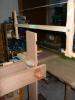

Just got a Lee Valley email with a method of work tip on compound angle joinery. As I look through the process, the author states to keep the edge of the plane on the guide block. However, there is just an 1/8 of an inch of edge before the blade starts. Just putting 1/8 of an inch of a plane on the block is tricky; furthermore with so little registering on the guide block how can the angle of the plane be held constant? Help me out with this one Neanderthals.

 Reply With Quote