Page 2 of 5 FirstFirst 12345 LastLast
Results 16 to 30 of 75

Thread: 15" Wide Belt Sander won't turn off

  1. #16
    Join Date
    Apr 2018
    Location
    Cambridge Vermont
    Posts
    2,289
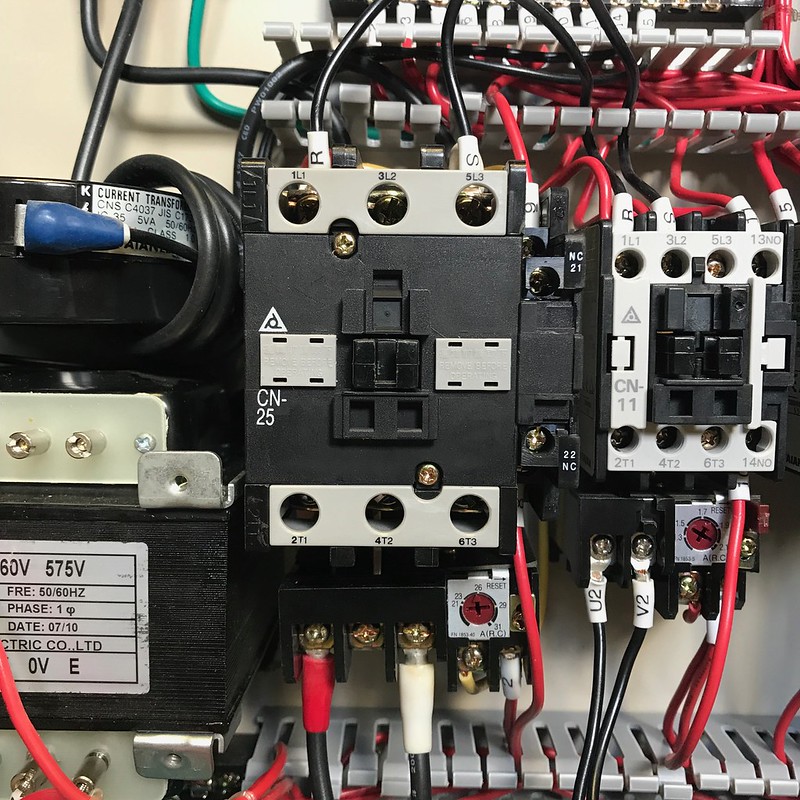
    According to the schematic if fuse 1 is removed and it runs then M1 AND M2 are either bypassed or the contacts are stuck. I can't see both of them going bad at the same time. Normally when they go bad they don't work. I've only seen one out of more than a hundred I've had to replace over the years at work that had the contacts welded closed. That was due to a motor that burnt up and the current draw far exceeded what the contacts could handle. The 'square' box on top of the contactor was stuck in the down position. The way contactors are made is the spring is under the contact points. So if they are fused shut the spring is compressed.

    Knowing this I just looked at the picture of the wiring and it looks like T1 and T2 look to be on the same side of the contactors and L1 and L2. If so that's your problem. They should be on opposite sides of the contactors.

  2. #17
    Join Date
    Nov 2007
    Location
    Richmond, VA
    Posts
    36
    Bill, thats correct, the contactor armatures remain out under power. Starting to think the PO did mess with the wiring based on the comments.

    Ron, below are some close-ups of the contactors as well as a shot showing where the power comes in. Think we may be onto something about the wiring having been messed with. Not sure why but knowing the PO as I do nothing would surprise me.

    Enclosure Labled by Josh Falcon, on Flickr

    Incoming Power by Josh Falcon, on Flickr

    Sanding Head Contact 2 by Josh Falcon, on Flickr

    Sanding Head Contact 1 by Josh Falcon, on Flickr

    Conveyor Contact 1 by Josh Falcon, on Flickr

    Conveyor Contact 2 by Josh Falcon, on Flickr

  3. #18
    Join Date
    Sep 2016
    Location
    Modesto, CA, USA
    Posts
    9,975
    The contactor switches and the overloads are bypassed. Power should come in to L1 then out to T1, L2 to T2, and L3 to T3 when it is pulled in. They do not use one contact number since there are only two hot leads in single phase power.
    The only confusion is that the overloads (if present) plug into the output (T) terminals then the output wires connect to the overloads.
    How many amps are the overloads set for, I can not read them from the picture. How does that compare to the motor nameplate amps.

    They have it set so that power comes in to L1 and L2 like it should. Then they have wrongly connected the output wires to L1 and L2. So they are just using the L-terminals as terminal strips.

    The way that panel is set up power should flow from top to bottom in each contactor then out the bottom to the load wires.
    Bil lD
    Last edited by Bill Dufour; 07-08-2020 at 2:41 PM.

  4. #19
    Join Date
    Sep 2016
    Location
    Modesto, CA, USA
    Posts
    9,975
    The sanding head contactor is using L1 and L3. The other two contactors are using L1 and L2. The forth terminal on the right side of the contactors is a low power switch, it may be low voltage as well. Likely for the control wiring or a pilot light. Possibly to a relay to turn on the dust collector.
    Bil lD

  5. #20
    Join Date
    Nov 2007
    Location
    Richmond, VA
    Posts
    36
    Thanks Bill, Alex. I think the PO bypassed the contacts based on what you all have pointed out and looking more carefully at the schematic. Any ideas why one might do this? Knowing the PO, I'm assuming something was wrong but instead of fixing it the guy just told his electrician to get it running as cheaply as possible. I'm going to try and revert everything back to the factory setup and we'll see where that gets us.

    As far as the overload relays, the sanding head looks to be dialed to about 26 amps, which should be about right. The conveyor looks to be set as low as it will go, below the first marking of 1.3A. I'll confirm the values on the motors and report back.

    Thanks again everyone. Hoping to get this sorted soon.

  6. #21
    Join Date
    Apr 2018
    Location
    Cambridge Vermont
    Posts
    2,289
    Did the PO have employees? It's possible that an employee thought that it was a planer that could take 1/8" off in one pass. The fact that they did both the sander and the conveyor tells me they didn't understand the tool. Get it wired correctly and then you can troubleshoot any problems.

    Even with the contactors bypassed they should still work. If you plug it in, reset the off button, then push in either one of the green buttons the contactor it controls should pull in. The white 'button' with the green ring around it I assume is the "power source" light to let you know the tool has power. Is it lighting up when plugged in? If not I'm guessing that the transformer is the problem. It doesn't look correctly wired. I think the S wire should be going to the "0" volt terminal on the top of the transformer. Just an FYI, the round transformer above the square one is what measures the current.

    As always unplug it before doing any work inside the electrical panel. Also I wouldn't use the Grizzly schematics as they look a little different. The one on the inside of the cover should tell you everything you need to know.

  7. #22
    Join Date
    Apr 2018
    Location
    Cambridge Vermont
    Posts
    2,289
    Here's my best guess on wiring. On the large contactor the two black wires (I can't see any markings on them), one red (1L1) and the other white (5L3) should be connected to terminals 2T1 and 6T3. On the contactor next to it the black wires on 1L1 (no label) and 3L2 (V2) should be connected to 2T1 and 4T2. All 4 of those wires look like they've been moved. The wires under the middle contactor that I suggested look incorrect look to be the R and S wires. They are black wires going to the left most contactor and from it to the center one. From there they used red wire. The one labeled R should go to fuse 1. They then call it R1 and it should be the wire connected to the 230v tap on the transformer. The other red wire labeled S should go directly to the 0v tap on the transformer.

    If that wire is not connected that's dangerous since it's one of your two 240 wires and it has no fuse on it. If it shorts to ground it'll trip your breaker. If you are connected to a 30 amp circuit that's most likely more than the smaller red wire can handle which could cause a fire. I wouldn't plug it back in until I could find that wire.

  8. #23
    Join Date
    Nov 2007
    Location
    Richmond, VA
    Posts
    36
    Thanks Alex, this is really good info, I appreciate you being so thorough.

    To answer your questions, the power source light doesn't come on under power, no. The amp meter gives a reading while running.

    Employees? Yes. While I was there everyone knew what they were doing, this machine ran fine. In the 2-3 years after I left and before I acquired the machine, no telling. My guess would be something went (maybe the transformer like you mentioned?) and instead of diagnosing/fixing it proper they went the least cost, "make it run" method. Sometimes a place for that approach, no doubt, not my first choice.

    Hoping to spend some time on it tonight and will follow up on your suggestions. Will report back where I land.

    Thanks again
    Last edited by Josh Falcon; 07-09-2020 at 2:45 PM.

  9. #24
    Join Date
    Nov 2007
    Location
    Richmond, VA
    Posts
    36
    So I was able to spend some time on the wiring last night. I think I have things back to how they should be. I tossed the Grizzly paperwork and used the diagram with the machine and I THINK I've got everything sorted. Below are some pics and notes on where things stand now;

    Alex, specifically in response to a few of your watch-outs,

    1) On sanding belt contactor, Red (1L1) and White (5L3) wires previously installed up top were connected to terminals 2T1 and 6T3 on bottom

    2) On conveyor contactor, black wires on 1L1 (U2) and 3L2 (V2) were connected to 2T1 and 4T2 on bottom

    Sanding Head Rewire by Josh Falcon, on Flickr

    Drive Motor Rewire by Josh Falcon, on Flickr


    3) I traced the R and S wires. Starting from the left most contactor (sanding head) they move to the center contactor (conveyor). R wire then runs through fuse 1, and then to the 230V terminal on the transformer The other red wire labeled S runs through fuse 2, then to the 0v terminal on the transformer.

    Fuses by Josh Falcon, on Flickr

    Transformer Detail by Josh Falcon, on Flickr

    So after I moved these things around and made sure everything was lining up with the diagram I plugged it back in and flipped the breaker and.............................nothing. This is what I was expecting considering where things started out. The power indicator light still doesn't light up so based on the comments it sounds like the transformer is shot?

    Any suggestions on how to verify that? Current from the 230v and 110V terminals? I pulled the transformer out just to see if there was anymore info on it but its just what you see in the pics. I tried a google search for the specific model number but didn't get anything. Can anyone tell me how to spec a replacement?

    Again, thanks for all the help.


  10. #25
    Join Date
    Nov 2006
    Location
    Holt Michigan
    Posts
    35
    On the sanding head contractor what are the gray rectangles that say remove before operating?

  11. #26
    Join Date
    Nov 2007
    Location
    Richmond, VA
    Posts
    36
    Quote Originally Posted by Jeff Dymond View Post
    On the sanding head contractor what are the gray rectangles that say remove before operating?
    Good question. Not sure. I imagine they've been there for the life of the machine but I've been wrong once before in regards to this thing.

  12. #27
    Join Date
    May 2018
    Location
    Lancaster, Ohio
    Posts
    1,364
    "I traced the R and S wires. Starting from the left most contactor (sanding head) they move to the center contactor (conveyor). R wire then runs through fuse 1, and then to the 230V terminal on the transformer The other red wire labeled S runs through fuse 2, then to the 0v terminal on the transformer."

    based on the pictures just posted and the above statement you have that wire in the wrong spot on the transformer
    the S wire needs to land on the top of the transformer (240 side)not feeding the fuse
    the #2 fuse should be fed from the bottom of the transformer (120 side)
    You should read 230(nominal voltage, actual anywhere from 210-240 actual) between them. Top of transformer
    To check the transformer once you have 230vac on the top, the bottom should output 120vac(nominal voltage, 100-130 actual)

    out of time will check back around midnight
    Last edited by Ron Selzer; 07-10-2020 at 12:07 PM. Reason: corrected what I said

  13. #28
    Join Date
    Sep 2016
    Location
    Modesto, CA, USA
    Posts
    9,975
    With the power on use a dry piece of wood, 12 inches long, to push in each contactor armature in turn and see if their motor runs. Wear real shoes and keep your other hand in your pocket while doing this. Also look at the control panel lights when you do this.
    Is that just a transformer to generate 110 volts? you could get power directly at 120 volts if you have neutral to the machine. Or is that transformer part of the big black coil transformer above that is to measure current draw?
    Since they did not bypass the lone contactor without overloads I wonder if the overloads are too small and kept tripping out. Checking for continuity through the overloads will not prove anything. I bet they conduct lower power fro ma meter with no problem and complain under full voltage and current.
    Hopefully the overloads are a standard size or if worst comes to worst a new DIN contactor and overload is not too expensive.
    Bill D

    Any chance there is a safety switch and it will not run with the control panel door open. My lathe is set up that way.It may be an OSHA requirement now. There is a safety switch like a refrigerator and the power switch must be rotated off for the cabinet door to open. It moves both a switch and a locking lever .
    Last edited by Bill Dufour; 07-10-2020 at 12:25 PM.

  14. #29
    Join Date
    Apr 2018
    Location
    Cambridge Vermont
    Posts
    2,289
    According to the schematic on the door the S wire shouldn't go to fuse #2. That's a problem. It should wrap around the current sensing transformer (the round one), go to the left most contactor, then to the center contactor, and finally to the upper terminal strip on the main transformer labeled "0" volts. Fuse #2 should have the 1 and 3 wires going to it. Fuse #1 also looks wrong. Opposite the R wire should be a wire labeled R1. That wire should go to the upper terminal of the main transformer labeled "230" volts. Right now wire "1" is doing that. Wire "3" isn't suppose to go to the main transformer at all. Wire "1" should be going from the lower terminal labeled 110v on the main transformer to fuse #2. It kind of looks like there's a second wire below the "2" wire on the fuse block. The "2' wire should never go to the fuse block.

    I think someone had no idea what they were doing. Possibly they changed a part like the transformer, got the wiring wrong, and then just did what they had to so it worked. I think what you are going to need to do is start tracing each wire out and make sure it's going to the correct location. If you aren't 100% comfortable doing so do you have a friend who can come over? It would be easier with a second set of eyes.

  15. #30
    Join Date
    Nov 2007
    Location
    Richmond, VA
    Posts
    36
    Quote Originally Posted by Alex Zeller View Post
    I think someone had no idea what they were doing. .
    That's highly possible considering where the machine came from.


    I'm going to take a step back and try to trace all the wires through the diagram. Truth be told, I follow about half of it, the rest I'm a little lost on. I may try to high-lite the wire paths on the pic and see where things are going astray.

    The S wire does wrap around the current sensing transformer, then to left most contactor (5L3), and then to the center contactor (3L2). After that (now red wire) it goes to the fuse and from there (now labeled "2") onto the 0V on the lower strip of the transformer. Sounds like that last bit is wrong per your's and Ron's comments.

    The R wire goes to the left most contactor (1L1), then to the center contactor (1L1). After that (now red wire) it goes to fuse and then (now labeled "1") onto the 0V on the lower strip of the transformer. Also sounds like that's incorrect.

    I need to trace back wire #3 currently attached to the transformer as well.

    I'll be back out there tonight to see what else I can sort through. I have a few other things to check out and questions to answer.

    Thanks again for everyone's help and patience, really appreciate it.

Posting Permissions

  • You may not post new threads
  • You may not post replies
  • You may not post attachments
  • You may not edit your posts
  •