Page 2 of 3 FirstFirst 123 LastLast
Results 16 to 30 of 32

Thread: Project: Auxiliary Bench for my Shop

  1. #16
    Join Date
    Mar 2003
    Location
    SE PA - Central Bucks County
    Posts
    65,879
    So at this point, the carcass is built, and the leveling adjustment mechanism is fabricated...time to move on to installing the casters

    IMG_5908.jpg

    After removing the "mobile" base from the carcass by taking out a few hinge screws and unbolting the bolts , I installed some 1/4" x 20 carriage bolts in the bottom-bottom panel to fasten the casters with. A few of them started to "turn" while putting on the nylon lock nuts, but I was able to grab the edges of the bolt heads with a plier and get all of them very snug.

    IMG_5911.jpg IMG_5912.jpg

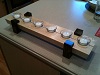
    I chose to use 1.25" long bolts because I felt that 1" was going to be a little too short for comfort. However, that meant I also had to grind off about 1/8" to keep the bolt ends from interfering with the swivel action of these 5" double-locking casters. It was like having some Fourth of July sparklers going for a few minutes, but an easy operation.

    IMG_5913.jpg

    That completed the assembly of the "mobile" and level-adjusting base...which I then painted black before putting it back on the case.

    IMG_5914.jpg IMG_5915.jpg IMG_5916.jpg
    Last edited by Jim Becker; 10-31-2019 at 9:04 PM.
    --

    The most expensive tool is the one you buy "cheaply" and often...

  2. #17
    Join Date
    Mar 2003
    Location
    SE PA - Central Bucks County
    Posts
    65,879
    The remaining work on the cabinet was to mill and install some solid stock edge-banding. I had a little bit of maple left over from the bench top, so I resawed that into quarters and planed the resulting pieces down into ~18mm wide by 10mm thick sticks. These are fastened using glue and 23 gage pin nails. As I always do for things like this, I take off directly from the case to get the exact lengths for a given component, mark the cut line, line it up with a saw tooth, back off the miter gage, start the saw and make the cut.

    IMG_5920.jpg IMG_5919.jpg IMG_5922.jpg

    About 30 minutes later, all the trim was on. I decided to do the back side, too, since I had the material and it would dress things up. Any remaining visible screws will get some spackle/filler before the paint goes on.

    IMG_5925.jpg IMG_5923.jpg IMG_5924.jpg
    Last edited by Jim Becker; 10-31-2019 at 9:11 PM.
    --

    The most expensive tool is the one you buy "cheaply" and often...

  3. #18
    Join Date
    Mar 2003
    Location
    SE PA - Central Bucks County
    Posts
    65,879
    The "cubby" on the right side of the case will get four drawers with full extension slides...which I ordered from Lee Valley today to take advantage of the current free shipping promotion. As with the case components, I use the CNC to cut the parts after making a quick cut list spreadsheet to be sure I had dimensions correct. These drawers are cut from ~.5" maple plywood and will have simple glued and screwed joinery just like I do for the tack trunks I make for folks. Very strong. After a very short period of time, I had all of the drawer parts cut and will likely assemble them tomorrow.

    IMG_5917.jpg IMG_5918.jpg

    These drawers will be faced with leftover 3/4" multi-ply from when I ripped out the miter station...seems appropriate since the bench will live in the same place. I will likely make full width pulls the emulate the same on the Husky tool cabinets I have nearby in the shop. The cabinet will be black for the same reason...hey, I'm a little anal sometime.
    Last edited by Jim Becker; 10-31-2019 at 9:17 PM.
    --

    The most expensive tool is the one you buy "cheaply" and often...

  4. #19
    Join Date
    Mar 2003
    Location
    SE PA - Central Bucks County
    Posts
    65,879
    Much progress today and moving toward the finish line...I just need the drawer slides to arrive so I can complete the installation of the drawers, get it off the bench and then do the mounting points for the bench top which will keep it about 165mm off the top of the cabinets so that my hold-fasts can be used with even the thinnest material.

    As I previously noted, the drawers are simple glue and screws assembly and are very strong. the front and back panels get installed first as shown to the solid bottom and then the sides go on. That leaves no visible plywood "end grain" showing from the sides once the applied drawer fronts are installed.

    IMG_5928.jpg

    I originally planned for four drawers but was able to sneak another one of the shorties up top with no problem...cutting the parts on the CNC only took about 5 minutes since I could reused an existing file with just moving a few things around to fit the piece of plywood I had left.

    IMG_5932.jpg

    Note the creative "bench extension" so I had enough space to assemble the taller two drawers at the other end of the bench.

    IMG_5930.jpg

    Since my small Sundown amplifier will live in the left side cubby, I needed to open up the back a little for both the electrical cord and so that the amp wasn't sitting in a box...amps like that are open at the back and that's part of the sound transmission. It also means ventilation for the tubes. Yup...it's a tube amp. The hole was simple to do with some pilot holes, a forstner bit from both directions to keep the corners clean and a jig-saw with a fine blade. "Shoulda coulda woulda" cut this on the CNC when I produced the back panel, but I just plain forgot. No matter...some other tools didn't feel so lonely since they got to do some work.

    IMG_5929.jpg

    To figure out the drawer front dimensions, I created a story stick and worked things out before cutting the pieces from multi-core plywood salvaged from the destruction of the old miter station. The top two faces are 53mm tall, the middle face is 105mm tall and the bottom two faces are each 155mm tall.

    IMG_5933.jpg

    I applied two coats of "relatively inexpensive" satin sheen water borne paint I grabbed off the shelf at True Value when I picked up the nuts and bolts for the casters. It was an easy job with a nice 2.5" brush and looks better than in these photos where it was only partially dry. I didn't paint the top yet as I want the ability to securely use glue for the mounting system I'll figure out for the bench top in the next few days.

    IMG_5934.jpg IMG_5935.jpg
    --

    The most expensive tool is the one you buy "cheaply" and often...

  5. #20
    Join Date
    Mar 2003
    Location
    SE PA - Central Bucks County
    Posts
    65,879
    I had a little time yesterday and today to faddle with this project in-between things like "mowing the leaves", etc. The focus is on the drawers and while I'm still waiting for the original four full extension slides to arrive from Lee Valley tomorrow or Tuesday, the one I ordered separately from Amazon when I added the fifth drawer was in hand last night. So I worked on the bottom drawer and that will serve as the procedural template for the remaining four drawers.

    I didn't take a photo of installing these first slides, but the cabinet mounted pieces are flush with the bottom of the case. I then calculated the position that the drawer mounted piece had to be up from the bottom to just clear the cabinet bottom and also the distance back from the front they needed to start to allow for applied drawer fronts to be flush. Once that was accomplished, the drawer was slipped into the case and the drawer front was applied. One of my steel rulers served as a spacer on the bottom very nicely while I clamped the drawer front in place and then drilled/countersunk from the inside and installed two screws.

    IMG_5944.jpg IMG_5946.jpg IMG_5945.jpg

    I decided to use some aluminum angle for full width drawer pulls that would look similar to those on the Husky tool cabinets already in my shop. Since Professor Dr. SWMBO and I had to run a few errands after dropping our older daughter off at work early afternoon, I picked up the metal at Home Depot for one the the day's stops. The angle is the 1/16" thinner style and is a 1" angle. 1.25" would have been "more ideal", but there was none in the rack. The metal was cut to the required 570mm wide on my miter saw that now lives upstairs near the lumber rack and then had any burrs removed with a fine file. The underside reveal is just enough to catch a finger and will also clean up the look of the top of the plywood drawer fronts.

    IMG_5948.jpg

    Attaching the aluminum to the plywood required five .125" holes to be bored and then countersunk for #6 screws. That's drill press work with the aluminum angle perched on a sacrificial piece of wood. The stops were used on the tool to insure that the countersinks were all the same depth and diameter.

    IMG_5949.jpg IMG_5950.jpg

    Installation of the pull is easy. I did carefully refine a few of the countersinks with a hand drill just to insure that all the screws were seated flush.

    IMG_5951.jpg

    Aside from paint, this bottom drawer illustrates how things will look. Once the other drawer slides are in-hand, it will not take too long to install the remaining drawers and then move on to getting the bench top supports on this cabinet and installing a vice on said bench top to complete the build.
    --

    The most expensive tool is the one you buy "cheaply" and often...

  6. #21
    Join Date
    Mar 2003
    Location
    SE PA - Central Bucks County
    Posts
    65,879
    I did also receive the vice hardware....this Yost unit was very reasonably priced and I'm impressed with the quality. It will be a "face vice" installed in the "end vice" position for this new work surface. If I need to use a front vice for something, I can do that on the main bench. In the mean time, I will not be backing into vice hardware when doing work on the main bench...which could hurt or something.

    IMG_5940.jpg
    --

    The most expensive tool is the one you buy "cheaply" and often...

  7. #22
    Join Date
    Feb 2009
    Location
    Bucks County, PA
    Posts
    975
    It's looking really good, Jim. I was going to say that cutting all that plywood with your CNC seems like taking the slow route, but then I realized you have almost no waste. That seems like a plus.
    And there was trouble, taking place...

  8. #23
    Join Date
    Mar 2003
    Location
    SE PA - Central Bucks County
    Posts
    65,879
    Steve, I would suspect it's chronologically faster to sling material onto the slider, but 1) I'd have to do a lot more lifting and manipulation and 2) the cuts are even more accurate on the CNC than on the slider. Assuming I program it correctly, of course. LOL I now make cut lists for this kind of project, but that still assumes I do the math correctly. I'm using Excel now for that because I can pre-measure material general thickness and use that in a simple formula to help make sure things fit together and end up at the desired total dimension. Example...the 2 sides of a drawer box that overlap the 2 other sides have to be exactly two material thicknesses longer than their side of the bottom in my design. The material thickness here was "generally" 12.43mm so the two referenced sides had to be 24.86mm longer than the drawer bottom. Doing that math in the spreadsheet helps me make less mistakes but is still fast. I just take those numbers and use them directly to create the rectangular vectors that will be cut by the machine. At that point, it's mostly organizing them on the sheet for cutting which is also pretty quick.

    Waste can be a factor no matter how one cuts. If I had a vacuum table I could reduce waste further, but as I've cut more and more with the machine, I've gotten a handle on just how many 'tabs" I actually need to keep a component in place so I can eliminate waste even more by getting things close together, even with overlapping "kerfs". One of the reasons that I don't like working with sheet goods that much is the weight frankly. At least with the tach trunks it's all .5" material and that's a little easier for me to handle. Here, I had one lift plus a twirl after the weight was reduced by removing cut parts. My main bench is adjustable height and it serves well to support the portion of the full sheet that's hanging off the CNC's ~4x~4 workspace. So instead of doing what I'd have to do to halve a sheet first, here I have one lift and cut parts a "few" minutes later.

    All of the parts from a half-sheet file were cut in 5-8 minutes tops and the programming time was mere minutes, too...it's just rectangles of a given dimension and since all are cut with the same tooling with the same settings, it's a "select all" setup to create the cut file for the machine. Once I built the file for one sheet, the other three were merely a quick modification of the sizes, etc., with the same "select all" to assign the same cutting parameters. The only thing that added a few minutes was calculating "safe" places for the small screws I used for holding the material to the machine's spoil board...a simple matter of moving a guide line in the software and noting its location at the edge of the sheet or its intersection with a perpendicular guide line for something in the middle of the sheet.
    Last edited by Jim Becker; 11-04-2019 at 9:16 AM.
    --

    The most expensive tool is the one you buy "cheaply" and often...

  9. #24
    Join Date
    Feb 2003
    Location
    Conway, Arkansas
    Posts
    13,182
    Love it! Looks like you're keeping that CNC machine busy.
    Thanks & Happy Wood Chips,
    Dennis -
    Get the Benefits of Being an SMC Contributor..!
    ....DEBT is nothing more than yesterday's spending taken from tomorrow's income.

  10. #25
    Join Date
    Mar 2003
    Location
    SE PA - Central Bucks County
    Posts
    65,879
    Quote Originally Posted by Dennis Peacock View Post
    Love it! Looks like you're keeping that CNC machine busy.
    Always..."to a hammer, everything is a nail" has a CNC corollary you know...
    --

    The most expensive tool is the one you buy "cheaply" and often...

  11. #26
    Join Date
    Mar 2003
    Location
    SE PA - Central Bucks County
    Posts
    65,879
    So....I continued with the drawers today once I got into the shop. Rather than doing fancy math to place the drawer slides, I built things up from the bottom and actually measured things as I progressed to insure that each subsequent drawer didn't interfere with the one below. I piece of scrap served as a spacer for the next slide up and that spacer got smaller and smaller over the process. )

    IMG_5956.jpg

    To get the position, I struck a line back from the top of the previous drawer and measured up from the top of the previous slide, adding a couple of mm for good measure. (pardon the expression )

    IMG_5957.jpg IMG_5959.jpg

    When done properly (wink...wink...nod...nod...) the slide would clear with a little space to spare.

    IMG_5960.jpg

    After screwing in the cabinet portion of the slide, I measured up from the previous drawer top to ascertain how far to set the drawer side of the slide up from the bottom. This measurement minus a couple of mm did the job. The front of the drawer mounted slides worked out to be 35mm back from the front of the drawer box to end up with the applied faces more or less flush with the front of the cabinet.

    IMG_5961.jpg

    This was once again a "rinse and repeat" until done operation...you can see that the last scrap spacer for the top drawer was indeed pretty narrow.

    IMG_5963.jpg

    And the end result...exactly what I wanted...

    IMG_5964.jpg

    To paint the drawer fronts, I had to remove the aluminum pulls, so I numbered them first so they returned to the correct drawer. The two 150mm drawers at the bottom and the two 50mm drawers at the top also have to go back to their specific spots because of minor variations in how the slides were installed. That's not workable for someone's kitchen, but fine for this "seat of my pants" project.

    IMG_5965.jpg
    --

    The most expensive tool is the one you buy "cheaply" and often...

  12. #27
    Join Date
    Mar 2003
    Location
    SE PA - Central Bucks County
    Posts
    65,879
    After Professor Dr. SWMBO (who was home today grading papers...) helped me lift the cabinet off the main bench, it was time to get the vice installed on the bottom of the bench top that will live on top of the cabinet. Using a piece of maple left over from building the top, I created the bench-side vice face (325mm wide and 40mm thick), located and placed the necessary holes for the acme screw and guides to pass through and fastened it to the edge of the bench. I actually fastened it twice...the first time on the wrong side which would have put the jaws toward the back of the unit...silly me forgot that things are reversed when upside-down. Fortunately, the glue had not dried and not too many bad words were required to recover. Blocking was also installed to support the bench-side portion of the vice from more of the scrap left over from building the top. I think I have one small piece a few inches long left. Efficient use of material I suppose.

    IMG_5969.jpg IMG_5970.jpg

    I'll make the movable vice face tomorrow...I need to raid my rack upstairs and find something interesting to use. To make that easier, I created a template using the bench-side piece before fastening it permanently to the bottom of the bench as shown.

    The final part of the job with the bench flipped over was to calculate where I wanted to put the supports that raise it up off the cabinet by about 165mm to allow sufficient space for the holdfasts to be able to grab onto very thin material. I'm still debating on two or three supports.

    IMG_5971.jpg

    As a matter of fact, I glued up three plywood sandwiches made from the last of the remaining material from the old miter station demolition. Once brought to final size, these will provide stout support for the bench top, whether I use two or three. The one at the vice end will understandably have to have material removed to clear the vice mechanism. One thing I need to pay very careful attention to is insuring that the supports, be there 2 or three, are all coplanar so there is no racking/twisting of the bench top when it's fastened down tightly to them. I predict that this project...will actually involve winding sticks which when you think about it is an interesting contrast to the CNC used to cut parts.

    IMG_5972.jpg
    Last edited by Jim Becker; 11-04-2019 at 9:01 PM.
    --

    The most expensive tool is the one you buy "cheaply" and often...

  13. #28
    Join Date
    Mar 2003
    Location
    SE PA - Central Bucks County
    Posts
    65,879
    WOOT! Got this thang finished up today and I'm excited to be able to start using it for its intended purpose as well as for other things that will benefit from the extra work surface.

    The laminations I made yesterday before stoping work for the day were cleaned up and sized before installing on the cabinet top. These add 165mm of "space" that will permit my hold-fasts to be fully functional even for thin material and also bring the work surface height from the floor to just a hair under 1000mm. (The MFT standard height is 900mm) This will be comfortable for detail work standing and reduce back strain due to minimal bending over. There are three supports. The two outer ones are fully engaged to support the top. The center one was left just shy so that I could employ some simple shims to keep the bench top from sagging over time without adding any stress to the same. The top of the cabinet has minor variations and the fitting to get all three supports completely in plane would have taken far more time than I was willing to spend. The two outer supports are screwed from below. I did not use glue for these just in case I decide I must change the overall height in the future after using it for awhile. The center support had to be "toe-nail" screwed because the center divider in the case is on the same line that screws from below would have had to have been installed.

    IMG_5977.jpg IMG_5978.jpg

    At that point, the top and supports were painted and it was off to vote.

    When I returned, I installed the top to the supports. One small shim was required back left and in the center, a small piece of used up 200 grit sandpaper folded over did the deed.

    IMG_5979.jpg

    I then put the aluminum pulls back on the drawers that had been painted at the end of the day previous and I'm happy to say I apparently didn't screw up with them...they went back to where they needed to be quite nicely.

    IMG_5980.jpg

    The final construction piece was to make the outboard vice face and get that setup. I had a nice hunk of straight grained 8/4 oak in the rack that was inexplicably the exact width I needed for height so that was chosen for the job. I planed that down to 40mm thick, did the layout for the required holes, bored them at the drill press and then went to work installing the piece to the vice.

    IMG_5981.jpg . IMG_5982.jpg IMG_5983.jpg
    --

    The most expensive tool is the one you buy "cheaply" and often...

  14. #29
    Join Date
    Mar 2003
    Location
    SE PA - Central Bucks County
    Posts
    65,879
    And...it's done.

    IMG_5984.jpg

    Moved it into place and checked for level. Only minor adjustment require...apparently at this wall, the slope is "greatly reduced". But I'm glad I have the ability to adjust for that if I ever have to move the bench for whatever reason.

    IMG_5985.jpg

    Overall, this was actually a very enjoyable "shop" project and it's certainly going to be useful. Unlike the big, fixed miter bench that use to live in this area, this work surface is mobile and has the flexibility that both the 20mm grid and .75" dog holes bring to work holding. The previous work surface there had none of that.

    IMG_5990.jpg
    Last edited by Jim Becker; 11-05-2019 at 9:07 PM.
    --

    The most expensive tool is the one you buy "cheaply" and often...

  15. #30
    Join Date
    Feb 2009
    Location
    Bucks County, PA
    Posts
    975
    Looks awesome, Jim. Great work!
    And there was trouble, taking place...

Posting Permissions

  • You may not post new threads
  • You may not post replies
  • You may not post attachments
  • You may not edit your posts
  •