Page 1 of 3 123 LastLast
Results 1 to 15 of 32

Thread: Project: Auxiliary Bench for my Shop

  1. #1
    Join Date
    Mar 2003
    Location
    SE PA - Central Bucks County
    Posts
    65,874

    Project: Auxiliary Bench for my Shop

    I've been threatening to build an auxiliary bench for my shop since the recent small renovation I did that removed the big, old miter station in favor of more shop space and a "dedicated" work surface for my guitar building. Well...yesterday, I started the task. While I plan a cabinet to be part of this setup, I'm starting with the bench top because I can use it on top of the MFT that's temporarily in service in that spot for as long as I need to since I want it to be a little higher up anyway.

    The design for the top is a general structure of maple with two 25mm thick MDF inserts that will be setup with a typical MFT-type grid of 20mm dog holes on 96mm centers. There will be one row of .75" holes down a piece of maple that will be about in the middle so I can use my hold-fasts when they are the right tool for the job. I may or may not put a vice on the top...most likely if I do, it will be on the end rather than the front face so I'm not banging into it. I may use a Moxon or other "attachable" vice on top of the other end for when that method of work holding is appropriate. Here's the basic idea for the top with some refinement still in the works:

    GuitarBenchTop.jpg

    I grabbed about 17 board feet of 6/4 maple yesterday from a local supplier and milled it up to use for the bench. The nominal thickness of the bench will be 65mm (about 2.5") and the width of each strip of maple is 35mm (not quite 1.4")

    IMG_5824.jpg

    While I established the general dimensions for the top in the above drawing and my head, there's nothing that substitutes for using the actual material that will be assembled together to ascertain exactly what the width is going to be. That started with laying a bunch of milled pieces next to each other so I could establish what the exact width would be. This was done at the end that is "solid" laminated maple...the utility area where heavier work can happen and where a vice might potentially live if I do decide on a face vice. Final width came in at 560mm which is about 22"...a narrower bench than my primary, but perfect for the intended task

    IMG_5825.jpg

    From there, I started cutting things to length, such as the shorter pieces that would be laminated for the solid end of the bench top. Using the stop on the fence insured they were all exactly the same size.

    IMG_5826.jpg

    It was then time to reassemble the laminated end to perfectly size the end piece that would be perpendicular to the laminations. I clamped things together tightly like they would be during the future final assembly and then measured with both the rule and by eye to get it exact. Three of these pieces get cut to the same length as the other end is a "double".

    IMG_5827.jpg IMG_5828.jpg

    That pretty much completed the cutting and allowed for the first dry-fit.

    IMG_5829.jpg

    It's easier to do sub-assemblies for something like this, so that's what I did...many clamps got to go to work here.

    IMG_5830.jpg
    --

    The most expensive tool is the one you buy "cheaply" and often...

  2. #2
    Join Date
    Mar 2003
    Location
    SE PA - Central Bucks County
    Posts
    65,874
    Those subassemblies were left to dry overnight and were all jointed flat to clean up the bottom and then got a very light pass through the planer to bring everything to identical thickness post-glue-up. I did a final dry check at that point and was satisfied...

    IMG_5832.jpg

    I chose to use 12mm Dominos to set things up so that all the top surfaces were indexed to each other. The tenons would also help keep things from slipping around as the glue up proceeded.

    IMG_5833.jpg

    Since one end would, as it were...end up...being "solid" all the way across and the other end would just have an end-cap, all the initial gluing was at the former end. Things slipped together one component at a time with some gentle persuasion with a soft mallet.

    IMG_5834.jpg

    A bunch of glue and a few minutes of time...along with some clamps...completed this task. At this point everything is assembled except for the end piece that caps the laminated end. More on that in a moment.

    IMG_5835.jpg

    The aforementioned end cap has to be treated differently because it is a true cross-grain situation where seasonal expansion/contraction can and will occur. So while it will be glued and pinned securely at the front edge with a Domino and well, glue...the two remaining connections will have to float, but be secure. There are two additional Dominos (middle and back) but they are in wider mortises with no glue so they cannot bind. I chose to use two screws to secure the middle and back of this end cap, installing them in recesses with oversize holes to allow that movement. The first step was to bore a larger recess that would ultimately be filled to hide the fasteners. A 25mm (about 1") Forstner bit at the drill press did that deed, creating a recess that is about 12mm deep. I further bored out the holes for the screws oversized. Glue was applied toward the front of this piece and then it was assembled and clamped to the remainder of the bench top assembly.

    IMG_5836.jpg . IMG_5837.jpg IMG_5838.jpg
    Last edited by Jim Becker; 10-24-2019 at 9:10 PM.
    --

    The most expensive tool is the one you buy "cheaply" and often...

  3. #3
    Join Date
    Mar 2003
    Location
    SE PA - Central Bucks County
    Posts
    65,874
    Ok, that leaves some impressive looking 25mm holes to fill. I don't have a dedicated plug cutter of that size but I have a big yellow machine that can make pretty much anything like this with a few minutes of programming and cutting. So I did. I cut plugs in 25mm, 25.02mm and 25.05 mm as I wasn't sure how precise my Forstner bits are. As it turned out, the Fische metric Forstner bits are "spot on".

    IMG_5839.jpg

    They were cut 15mm deep and I sliced them off at the bandsaw leaving just enough to be able to sand them off flush

    IMG_5840.jpg IMG_5842.jpg

    While I had the CNC running, I cut the 25mm MDF inserts for those big open areas on the design. I then recut one of them because I'm stupid and mentally said that 176mm was 171mm. These machines cut exactly how you tell them to. LOL

    IMG_5844.jpg

    At the end of the day, I have a glued up maple bench top assembly ready for the inserts. From here, I need to get the inserts, um...inserted...and create a basic structure that holds them flush yet allows them to be replaced in the future should they become damaged. I may take the whole thing out to get two quick light passes through a wide sander to completely level things. And finally, the whole thing will go on top of the CNC and all the dog holes will get cut.

    IMG_5845.jpg
    Last edited by Jim Becker; 10-24-2019 at 9:17 PM.
    --

    The most expensive tool is the one you buy "cheaply" and often...

  4. #4
    Join Date
    Feb 2009
    Location
    Bucks County, PA
    Posts
    975
    Looking good, Jim. Great explanation and pics. Looking forward to more progress on this.
    And there was trouble, taking place...

  5. #5
    I really like the inserts that you are planning, I want to do the same thing but with steel on a general purpose bench. I understand the floating connections on the "solid" end of the bench, but how do you account for the movement at the end of the bench where the inserts will be placed? The cut out width for the inserts at the insert end would basically stay the same all of the time since there is very little cross grain connection but the "solid" end will expand and contract basically giving you a trapezoid of different dimensions depending on the time of year. Is this a concern with the intended function of the bench or is it negligible in such small areas? For the bench I am planning that would be negligible, but others need much more precision.

    Very nice looking build, I like how you easily break down the steps for your projects in each post.

  6. #6
    Join Date
    Mar 2003
    Location
    SE PA - Central Bucks County
    Posts
    65,874
    Dylan, you raise a good question relative to the inserts. Even though the MDF (which in this case is leftover Extiera exterior rated stuff) doesn't "move" much, the maple might so width-wise, I left a tiny bit of accommodation for that movement by slightly narrowing the inserts when I cut them.

    Do be careful with steel on a bench if you use any "sharpy-pointy" tools...

    The bench top is actually complete and I'll be posting more photos tomorrow.
    --

    The most expensive tool is the one you buy "cheaply" and often...

  7. #7
    Join Date
    Mar 2003
    Location
    SE PA - Central Bucks County
    Posts
    65,874
    So...day two and the final day for this auxiliary bench surface has come and gone...

    Because I (mistakenly) assembled this on my current main bench top which is in desperate need of replacement...it's not flat, has too much metal in it (accidentally) to allow truing with hand planes and no longer meets my needs)...I had a very slight twist to the assembly after glue-up. It wasn't much, but it was something that I couldn't leave in a brand new work surface. So I put it on the CNC to "level" one side (I chose the top since it would also clean some things up a bit) and had to do it in two steps because the assembly was about 5" longer than my effective cutting area. The first step was to do as much as possible that included the solid laminated portion and then "sneak up" on things for the last few inches after flipping it around. It didn't have to be "perfect" looking because it was going to a wide sander afterward, but it had to have the twist gone so I had a flat reference surface. This photo is after completion of both steps.

    IMG_5847.jpg

    Then I was off on errands including taking it to my friends at Bucks County Hardwoods to get sanded. It got a couple of light passes with the now-flat top down to insure the bottom was parallel to the top and then a couple passes to really clean up the top side....about 1mm off both sides in the end with a final thickness of 62mm. (~2.45")

    IMG_5849.jpg

    Back to the shop and then it was time to install the supports for the panels. There are corner blocks to permit screws to hold in the panels and some narrow stock down the edges to permit the panels to have support all around. I forgot to take a photo after installing these elements. The work was done on top of the CNC bed that had just been "cleaned off" making it "perfectly" flat so I could get as close as possible to the panel surface being at the same level as the maple portions of the construction. If anything, I preferred having to shim up rather than shave down, if you catch my drift.

    IMG_5850.jpg

    That done, the assembly was flipped over so I could measure, drill/countersink and screw down the top.

    IMG_5851.jpg IMG_5852.jpg

    I did need to do a little shimming at a few of the corners...used up sandpaper got the nod because, well...it was right there where I could grab it. You can see the support structure for the panels in this shot that I wasn't able to show previously.

    IMG_5853.jpg

    At that point, the bench was completed...at least the building part...and it was time to move on to the truly scary operation: boring a bunch of holes in the right places

    IMG_5854.jpg
    --

    The most expensive tool is the one you buy "cheaply" and often...

  8. #8
    Join Date
    Mar 2003
    Location
    SE PA - Central Bucks County
    Posts
    65,874
    I had already done a "plan" for the bunches of dog holes in the CNC design software before I started building this but because the final dimensions were fluid, it was necessary to revisit the file and change things to match the final physical structure exactly so that all the "boring" business happened in the correct locations. This includes some slight adjustment laterally to insure the mounting screws for the panels were not in play. I actually added a second full row of the .75" dog holes down the wider front edge. Additionally, a third short row of the same were placed toward the back of the solid laminated portion of the bench in case I decide to put a face vice down at that end. I still have not decided on vice accommodations and probably will not until I design and build the cabinetry for under it.

    Here's the hole design I finalized on for both the 20mm holes on 96mm centers in the panels as well as the rows of .75" holes in the solid stock This combination makes for great flexibility and I'm considering this general idea for the replacement top for my main bench, too. The singular reason I want/need the .75" holes is for my beloved hold-fasts. (and a couple of really nice brass dogs I sometimes use for hand-plane work)

    IMG_5859.jpg IMG_5858.jpg

    Given the finalized design it was time to take a deep breath, strap that thang onto the CNC and "press the button". Hold-down was interesting for something this "thick". There was not a huge amount of downward force required because the bench has quite a bit of weight, but some was necessary to counter any minor "lifting" that comes with up-cut tooling. (These holes are too deep to use anything but up-cut for chip clearing) More importantly, screwing down support along the edges of the construction insured it could not move in any direction. While this bench top is a few inches longer than the maximum cutting area of my machine, the pattern of holes all fell within those limits

    IMG_5855.jpg

    And so it begins...

    IMG_5856.jpg

    And continues...

    IMG_5857.jpg

    After the holes were all bored (20mm holes completely through the MDF panels and the .75" holes 40mm deep...the max for my .375" cutter...in the maple), the edges of the holes were slightly chamfered with a 90º v-bit.

    IMG_5860.jpg

    And...now the work is almost done...

    IMG_5866.jpg
    Last edited by Jim Becker; 10-26-2019 at 11:18 AM.
    --

    The most expensive tool is the one you buy "cheaply" and often...

  9. #9
    Join Date
    Mar 2003
    Location
    SE PA - Central Bucks County
    Posts
    65,874
    Since I couldn't bore the .75" holes all the way through the solid maple due to cutting depth constraints on my longest .375" end mill, the work had to be completed with a drill bit. Easy enough...clamp a waste board on the bottom to prevent tear-out and then cut the final bit of material out with a sharp Forstner bit. Rinse. Repeat.

    IMG_5868.jpg IMG_5869.jpg

    And now the assembly is complete including all the dog holes and ready for sanding, etc.

    IMG_5870.jpg

    A "test fit" for the intended space that this work surface will occupy most of the time. It will be on top of the MFT temporarily until I get the permanent cabinet built. That will actually help with the design of that cabinet because I can ascertain if the "general" height is appropriate for the work I intend to do on this surface. It's a bit higher than a common bench height, but most of the work lends itself to that. I may or may not make it variable height.

    IMG_5872.jpg

    As is my custom with bench surfaces, everything got an application of BLO which is renewable at any time. I'm very pleased with the end result...

    IMG_5873.jpg . IMG_5874.jpg

    And for the completion of this phase of the overall project...I'll leave you with this nice wood porn.

    IMG_5875.jpg
    Last edited by Jim Becker; 10-26-2019 at 11:25 AM.
    --

    The most expensive tool is the one you buy "cheaply" and often...

  10. #10
    Quote Originally Posted by Jim Becker View Post
    Dylan, you raise a good question relative to the inserts. Even though the MDF (which in this case is leftover Extiera exterior rated stuff) doesn't "move" much, the maple might so width-wise, I left a tiny bit of accommodation for that movement by slightly narrowing the inserts when I cut them.

    Do be careful with steel on a bench if you use any "sharpy-pointy" tools...

    The bench top is actually complete and I'll be posting more photos tomorrow.
    Thanks for the reply, I figured you had accounted for that. As for my bench, I am planning a 2' square steel insert in a bench that will likely be 5' x 10'. If I get too close to the steel with any sharp tool it's my own fault

  11. #11
    Join Date
    Mar 2003
    Location
    SE PA - Central Bucks County
    Posts
    65,874
    That's not a bench you're planning, Dylan...that's a bowling ally!
    --

    The most expensive tool is the one you buy "cheaply" and often...

  12. #12
    Join Date
    Apr 2017
    Location
    Michigan
    Posts
    2,772
    Great build along Jim, and a nice bench. The CNC really works for you.

    I'm not clear on the accommodation for wood movement. In your second post you say "oversize holes" but the pictures don't show that.

  13. #13
    Join Date
    Mar 2003
    Location
    SE PA - Central Bucks County
    Posts
    65,874
    Quote Originally Posted by Tom Bender View Post
    Great build along Jim, and a nice bench. The CNC really works for you.

    I'm not clear on the accommodation for wood movement. In your second post you say "oversize holes" but the pictures don't show that.
    The pilot holes in the end pieces that the screw shanks are in are 1/4" despite the screws being #10. I modified the countersink so that the heads had some movement, too. That's just not clear in the photos unfortunately.
    --

    The most expensive tool is the one you buy "cheaply" and often...

  14. #14
    Join Date
    Mar 2003
    Location
    SE PA - Central Bucks County
    Posts
    65,874
    This week's little project is to build the cabinet that will be supporting the bench top already completed. Aside from producing a few prototypes for a client, I had a little lull in paid work and that's always a nice excuse to work on something for my own benefit. Aside from things like drawer slides of the appropriate length and a few fasteners, I had all the material for this project in my racks.

    The carcass for the cabinet was cut out of a sheet and a half of .75" "shop grade" plywood I had hanging around. Since I have the CNC, I decided to use that rather than slinging it up on my slider. Sheets are heavy. Lifting once is enough. And contrary to past sheet goods projects, I left them at their ~97" long and adjusted my bench to the same height as the CNC bed to support the full sheet, even though I was only cutting on half of it at a time. Since I had already done an informal "cut list" for the components, it only took a few minutes to create the files and then cut out the parts...I was taking my time, too.

    IMG_5892.jpg IMG_5893.jpg IMG_5894.jpg IMG_5895.jpg

    Once one end of the sheet was consumed by the parts I had planned for it, I flipped things around and cut the parts planned for the other end. A .25" compression bit was used with two passes for the .75" material. I "can" probably cut full depth for this material at a slower feed rate, but with a likely reduction in quality. I like to cut the first pass with a .02mm allowance and the the second and final cut gets the rest of the depth while also cleaning the entire edge. As side from sanding the small areas where I used tabs to hold the piece in place in the sheet (I don't have a vacuum table), the edges were "glue up ready, more or less. This is the pile of components resulting from the cutting so far...

    IMG_5896.jpg

    The design of this cabinet includes a base that can be leveled in both directions. Why? Because my shop floor slopes...the building was originally constructed as "mostly garage" by the previous owners. I decided I didn't want to have to deal with things like shims which are a pain when wheels are involved, too. So to accommodate the idea I had for adjusting level, the base/bottom pieces are longer than the carcass, leaving about 35mm at the end for a couple of bolts that will secure things at a particular height. Assembling the box would be with screws and glue. Here I'm marking the end panel location so I can pre-drill for screws that will come up through the bottom since this panel has to sit on top of the base, rather than fasten to the end like at the other end. (Disclosure...I forgot to make this panel about 18mm shorter in my cut list to account for being on top of the base panel, so I had to trim it off prior to assembly) I then used the markings to put in pilot holes as shown and then countersunk on the bottom (not shown) for the screw heads. During assembly, I run the drill/countersink back through into the vertical panel so that the screws will not split that panel.

    IMG_5897.jpg IMG_5898.jpg

    Assembling the case bottom and that one panel required a little setup....but it worked out nicely. Apply glue, use a few brads to hold it in alignment and then run in the screws.

    IMG_5899.jpg
    --

    The most expensive tool is the one you buy "cheaply" and often...

  15. #15
    Join Date
    Mar 2003
    Location
    SE PA - Central Bucks County
    Posts
    65,874
    With that one end panel installed, I could change the orientation so that the bottom was, um...on the bottom...and fasten the other end panel using glue and screws on the end of the base component.

    IMG_5900.jpg

    The "top" was then put on the bench and the previous assembly inverted onto it, glued and screwed from the ends.

    IMG_5901.jpg

    I did have to trim down the back panel as once again, my cut list was too generous...which when you think about it is much better than too stingy. Board stretchers just don't seem to exist. 
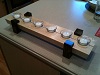
Once the back was in place a partition was installed to complete the basic cabinet carcass.

    IMG_5902.jpg

    Yea, it's a box. Really exciting by itself. But the next part is much more interesting. Remember I mentioned a leveling feature? That's what's coming now.

    The case bottom has a clone piece of exactly the same size. It will be fixed to the case bottom with hinges at one end and an adjustable stop system using two carriage bolts at the other end. To start this part of the project, I temporarily clamped the second bottom to the case bottom so I could do several things including building up support for the hinges at one end and drilling perfectly aligned holes for the carriage bolts at the other end. Here you can see the start of the hinge support which will be several layers of plywood with a triangular piece of solid stock.

    IMG_5903.jpg

    To allow for longer fasteners for the screws into the case as well as to provide enough clearance for leveling both left-to-right and right-to-left, I added a piece of .5" plywood to the bottom of the case. This block combined with the way the surplus entry door hinges were designed allows for 28mm between the two "bottoms" and a good bit of leveling adjustment in either direction. I'll really only need about .375-.5" over the length of the bench adjustment, depending on "where" in my shop the bench is positioned, and the available space is wide enough to be able to have a solid shim I can slip in there at the exact thickness needed to provide more support than the bolts alone over a long period of time in the anticipated bench position it will normally live.

    IMG_5904.jpg IMG_5905.jpg

    Here you can see the adjusting end with a temporary 28mm shim for "true" level while the bench is on the bench, as it were.

    IMG_5906.jpg
    Last edited by Jim Becker; 10-31-2019 at 8:55 PM.
    --

    The most expensive tool is the one you buy "cheaply" and often...

Posting Permissions

  • You may not post new threads
  • You may not post replies
  • You may not post attachments
  • You may not edit your posts
  •