Those thin bushings are the problem, I had the same trouble using a 13/16” bushing with a spacer bushing and 3/4 shank chisel.


 [OP]
Contributor
[OP]
Contributor
Those thin bushings are the problem, I had the same trouble using a 13/16” bushing with a spacer bushing and 3/4 shank chisel.
Bumbling forward into the unknown.
[OP]
Contributor
Well finally I’ve decided time to make a chip blower for the Wadkin. I’ve planned it out so that it will start with travel and and end after travel so as to give the air compressor recovery time.
Bumbling forward into the unknown.
Guest
Most of the old American machines used the fan off the motor to generate the breeze.
[OP]
Contributor
Most Japanese do also. This machine doesn’t have a fan. This one will have 100psi through .080” nozzle so it will be quite effective and clearing chips and keeping the chisel cool.
Bumbling forward into the unknown.
[OP]
Contributor
Concept: this will mount to the top of the motor, the roller bearing will engage the machine ways and depress a valve. Simple enough.
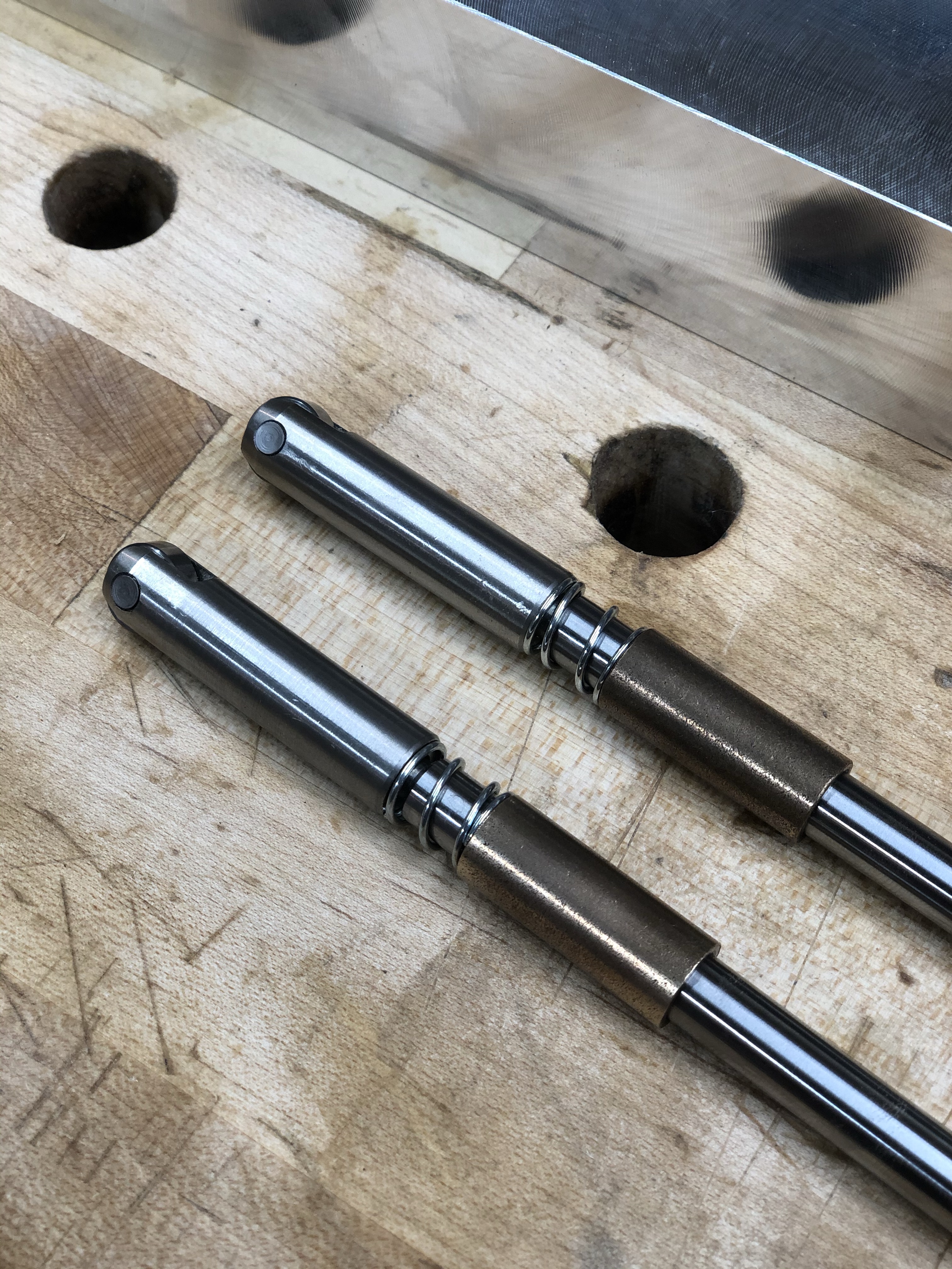
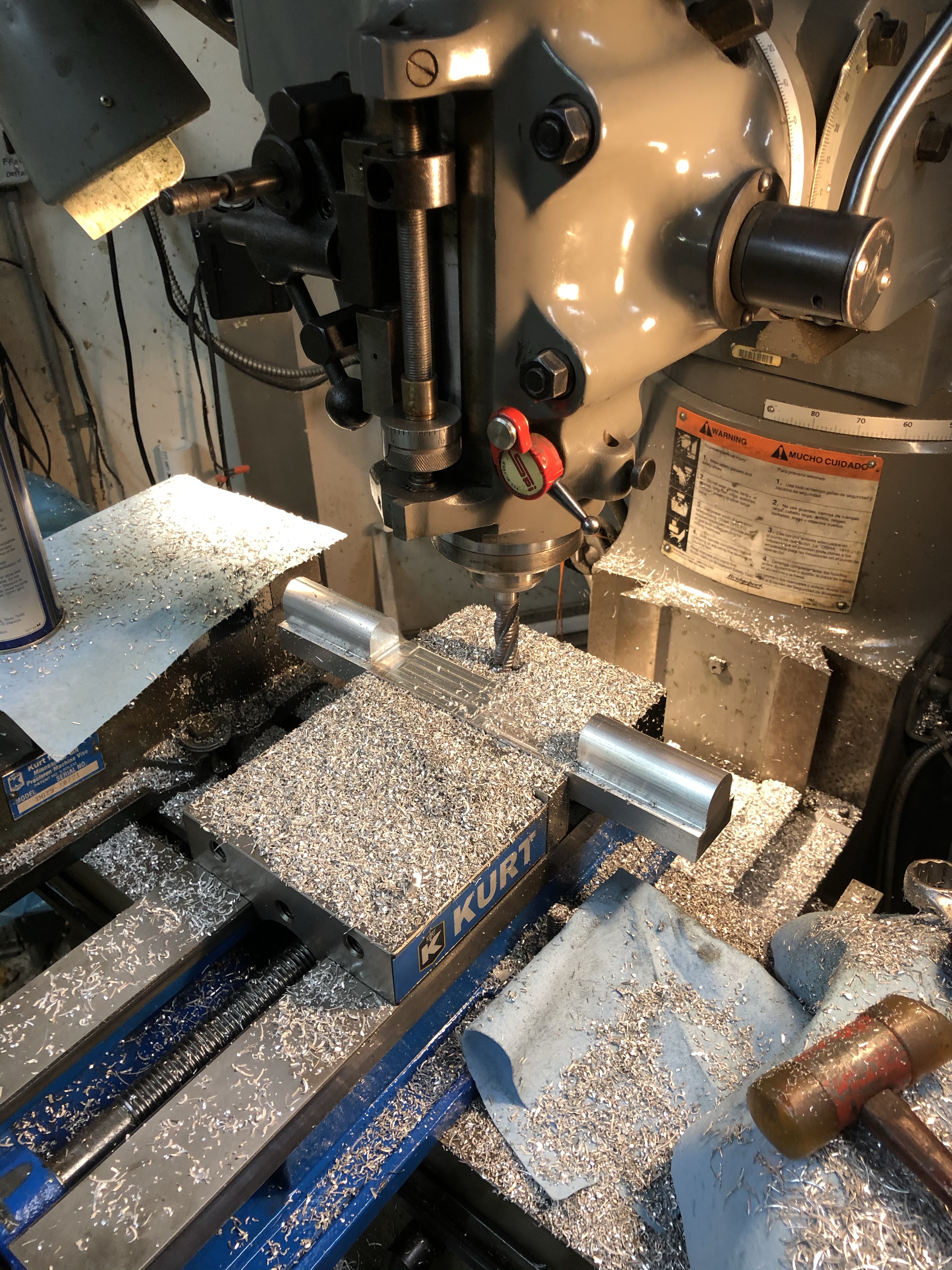
I found some stainless steel standoffs made for optical equipment that were the right dimensions but needed to made you accommodate bearings. So I slotted them on the Bridgeport, drilled them then reamed for pins. The pins are a press fit so as to eliminate hardware. I recognize that these look like lifters, hah. Next these are attached to hardened steel shafts. The shafts will ride in a bronze bearing and a spring will be housed in the assembly.
I had to position the shaft out of direct alignment with the pressure valve so in order to account for that I will be making a bronze pad which will also double as a way of aligning the bearings.
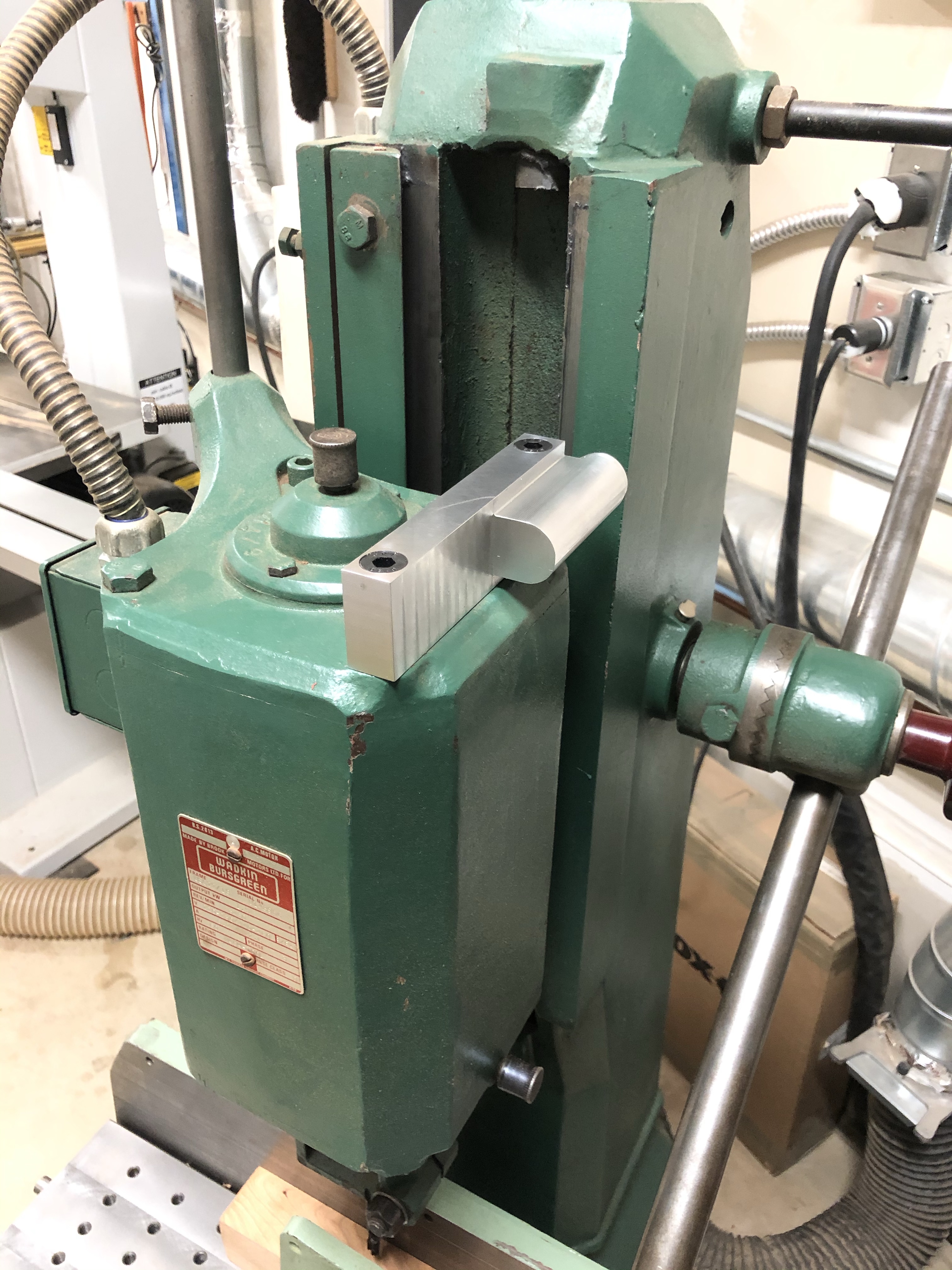
The valve hasn’t delivered yet but the ‘cool arm’ has. This thing is neat, tighten the bolt and it locks the entire part’s position.

Bumbling forward into the unknown.
Member
This is awesome Brian! Where did the 'cool arm' come from?
Guest
Brian,
You are a special guy
In all seriousness I absolutely 100% mean that lol..
No but seriously those pins with the bearings at the end are the exact design as to what the rip fence of my Martin travels on. The sub fence is a triangle. There is one of those at the tip and one on either side of the triangle at the back or users side. They adjust up and down using a set screw.
Pretty nifty stuff you come up with. Like I said your wicked smaht as they say here in the Boston..
IMG_1505.jpg
IMG_2130.jpg
Last edited by Patrick Walsh; 12-24-2019 at 8:05 AM.
[OP]
Contributor
Thanks Jeff! The cool arm is from Noga, same company that makes the indicator holders.
Bumbling forward into the unknown.
[OP]
Contributor
Hah, thanks Patrick. Glad to see that Martin uses a similar solution.
Bumbling forward into the unknown.
Guest
My guess at this point “considering” is it must be a common solution for such applications and I am or have just not been in the know?
Originally Posted by Brian Holcombe

[OP]
Contributor
I wouldn't say it's super common on woodworking equipment, but it seemed like a good way to attend to this. The roller is there to overcome the square edged transition from 'extended' to compressed and do so without a ramp, so a roller bearing made sense. I would have been happy using a bronze slug but then I'd have to make a transitioning piece.
I think it's a good choice where something is exceptionally heavy (or spring compressed in my case) and must still move nicely.
Bumbling forward into the unknown.
[OP]
Contributor
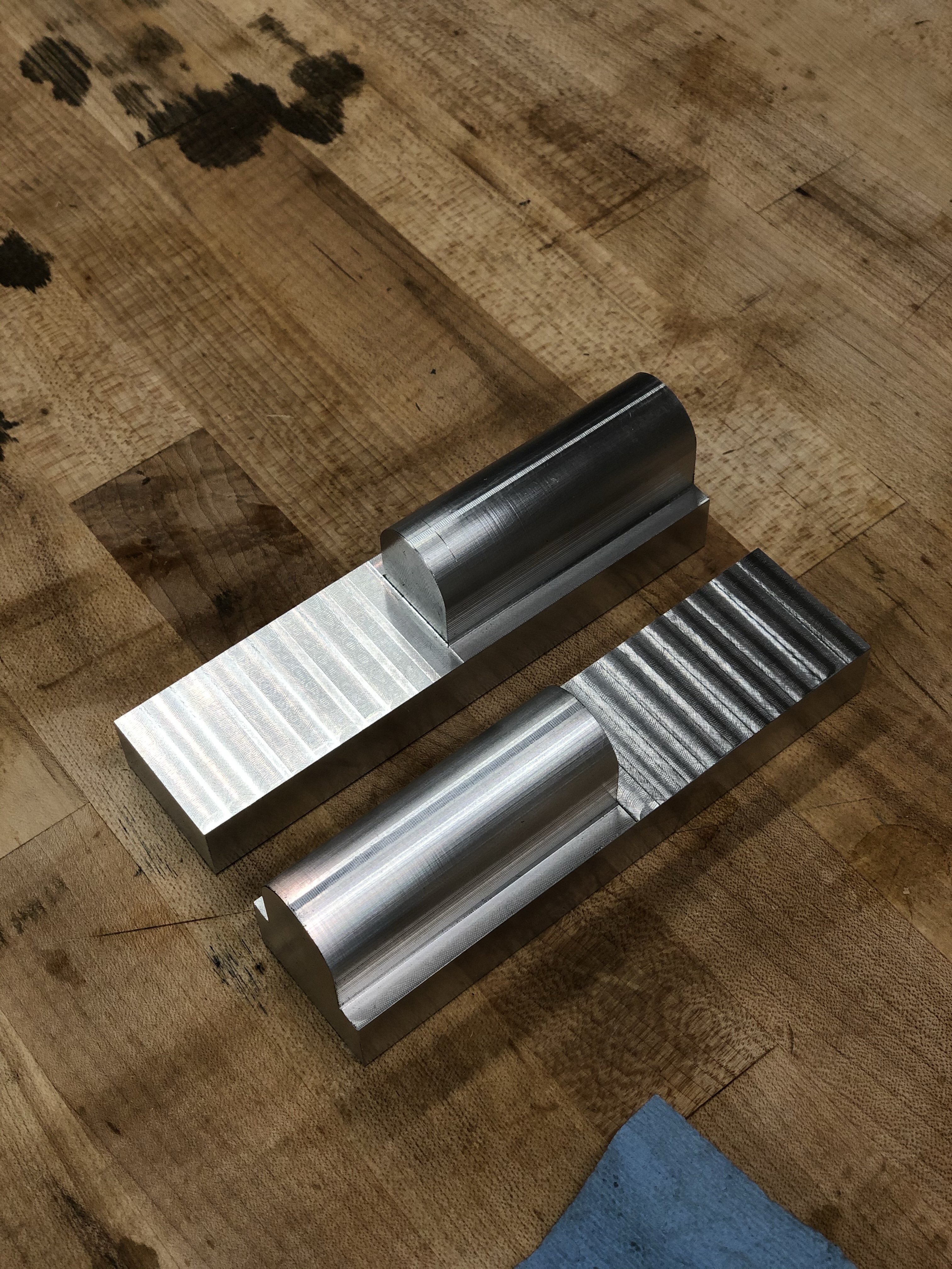
Evolving this design a bit;
Ive been debating wether to make the bearing housing totally round in the part that extends past the mount. I think it would be a nice touch but I’m not sure that I have the setup for it.
Bumbling forward into the unknown.
[OP]
Contributor
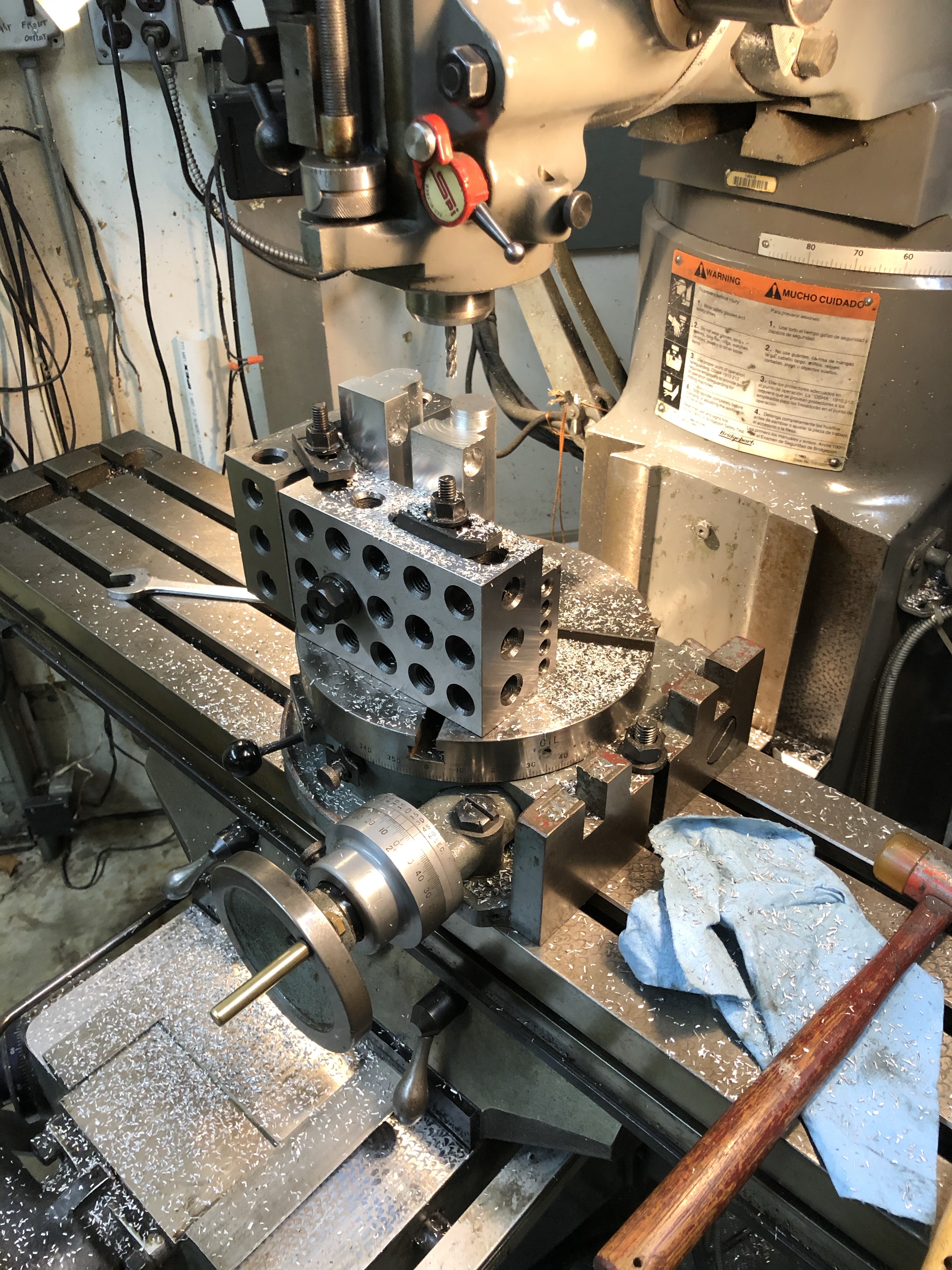
Bit of progress. Using manual mills one is reminded that each detail can be multiple setups. Still this felt worth it.
This looks awkward without the other components but should give a reasonable idea of what I have in mind. A two way air switch will attach to this and it will be depressed by the roller bearing/spring setup.
Bumbling forward into the unknown.
 Moderator
Dang, rounding off that end really makes for a visually elegant component!
--
The most expensive tool is the one you buy "cheaply" and often...
[OP]
Contributor
Thanks, Jim! I've been aiming at keeping this in appearance with the machine, it has a lot of smoothed spots. I made a little collar on the end there, and not sure If I should improve upon that a touch before I move on.
Bumbling forward into the unknown.
 Posting Permissions

 Reply With Quote