I've thought about those little mag blocks to mount a dust port. Make a base that a hose clamp and the mag block could attach to?


 Member
I've thought about those little mag blocks to mount a dust port. Make a base that a hose clamp and the mag block could attach to?

 [OP]
Contributor
[OP]
Contributor
Thanks gents, I'm thinking of hanging a bar off of the stop mount's bolts which would retain a 5" diameter dust port (for no other reason than I dont want to change sizes). Ideally it could be made in a way that retains the tubing by a neat clamp which can be loosened and readjusted if it's in the way of a job.
I'd like all the modifications to be bolt-on, bolt-off so that the machine itself remains unchanged. I received it in great shape and want to maintain that, unlike the Maka which needed to be gone over soup-to-nuts and was in rough appearance so I had no reservations with making changes there.
Bumbling forward into the unknown.
 Moderator
Brian, maybe consider a magnetic connection for the 5" hose to be able to move it efficiently. Someone recently posted about a solution in Workshops for that.
--
The most expensive tool is the one you buy "cheaply" and often...
[OP]
Contributor
Thanks Jim, the magnetic port looks like it solves a slightly different problem.
Bumbling forward into the unknown.
[OP]
Contributor
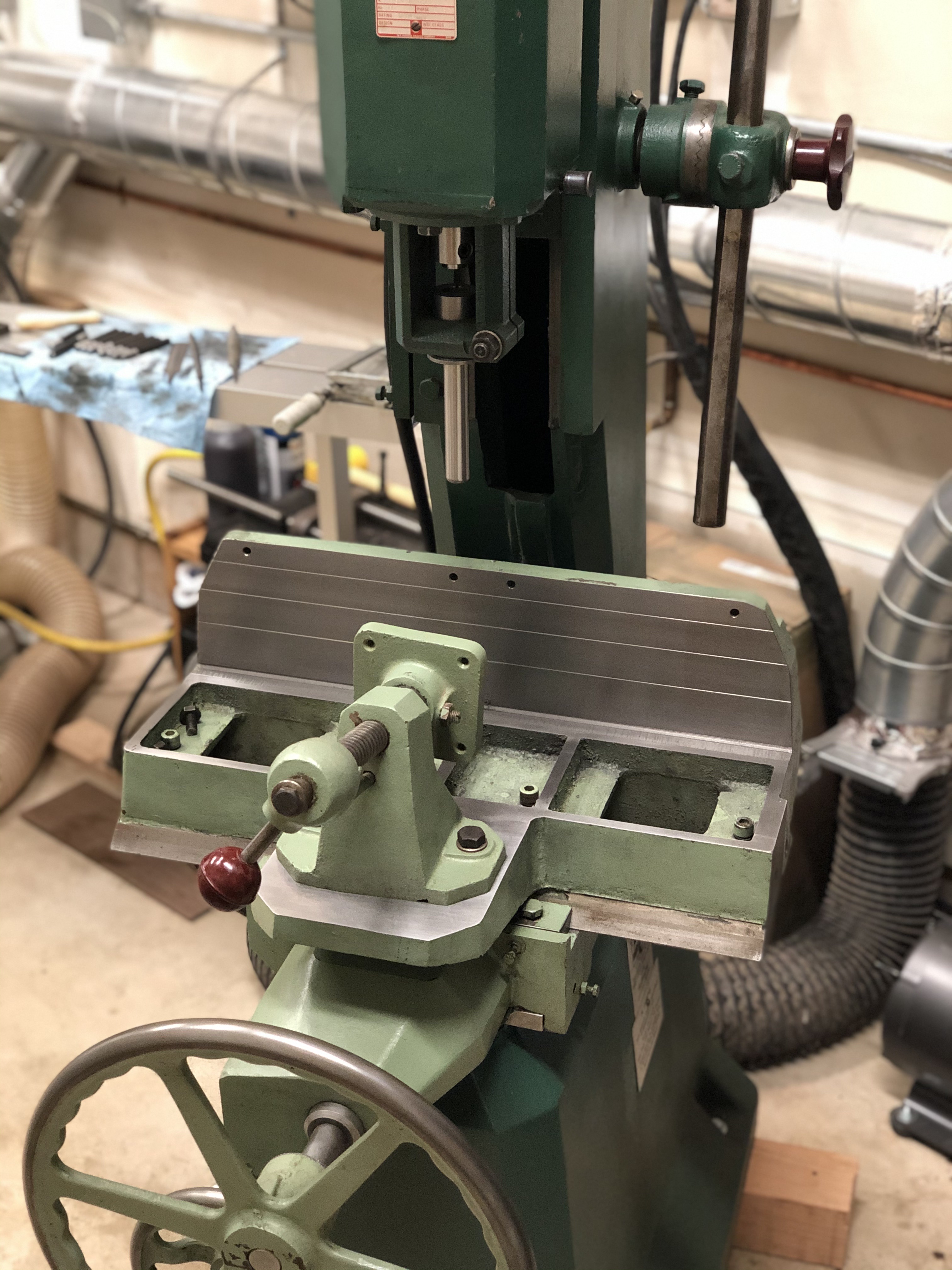
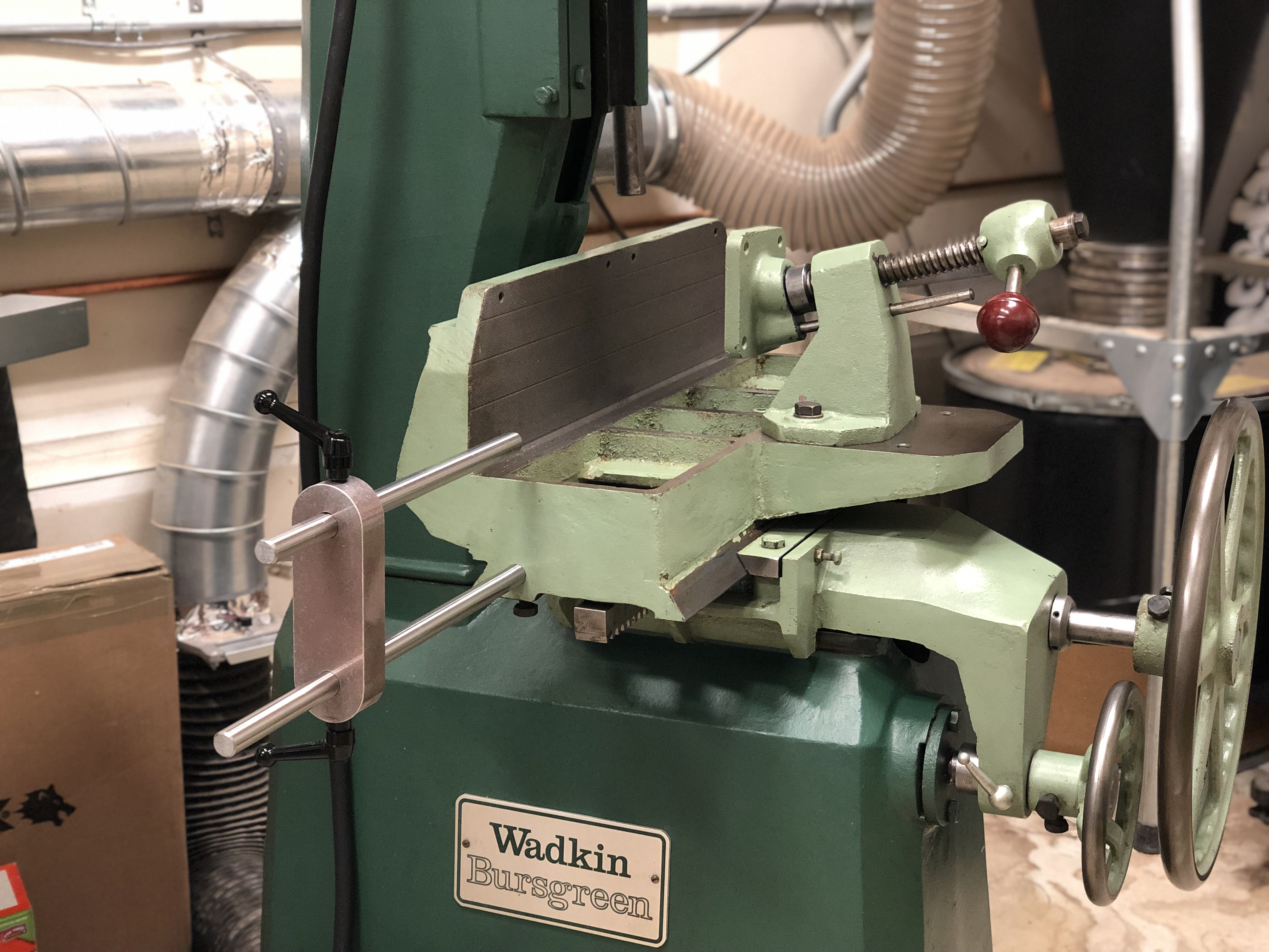
Here's what I made for a stop, so far. Basic system. The arm places the rod 1" above the table, so I may need to make additional arms for other setups.
I bought a vibratory tumbler recently so I've been hunting for this to put in it and finish. Imparted a unique finish upon this aluminum, this was bright off the machine but I wanted something complimentary of the styling of Wadkin. I used ball end handles for that same purpose.
Bumbling forward into the unknown.
Contributor
That machine looks in excellent condition Brian. And a little newer than mine.
I see you are using the rods for table movement sideways to support the table stops. Clever use of those.
Have you seen the original Wadkin stops that bolt to the holes in the top of the fence? A DM sold in Colorado last year that had these. Pretty rare to find those stops.
[OP]
Contributor
Thanks, Joe!
I have seen the original stop setup and I like how it looks. Probably a great setup for production work where the stops can be set and flipped out of the way for multiple parts. In my case I'm finding that a micro-adjuster is more helpful for this kind of machine. Similar to what I made for the Maka, which I found really useful for dialing in a setup.
Often enough when I make a batch of parts I'm scribing my setup part to a knife line, then bringing the part to the tool at that knife line. A micro adjuster is super handy for that, so I feel a rod-stop could be more easily micro adjusted in this case. It could be made as simply as tapping and installing a thumb screw and thumb nut.
Bumbling forward into the unknown.
Contributor
Brian, micro adjust of the stop would be a nice feature. The original Wadkin stops would be desirable to me for left and right door work but understand furniture making brings on different needs.
I sharpened my 12mm chisel today and tried rounding the edge slightly of the cutting edge of the auger. Seemed like it ejected the chips a little better but think I need to round more. I did not round at the cutting edge. Hard to tell but your picture looks rounded right up to the cutting edge. And rounded fairly heavy.
I chopped quite a few mortises today and kept a eye on the chips. Jeff’s suggestion of DC on both sides of the chisel is a good one.
[OP]
Contributor
Certainly, I can see where they would be fantastic for door making.
Round is a pretty good amount, I rounded a smooth transition into the flat but without affecting the flat as it nears its cutting edge. On blind mortises I let the auger past the chisel by about 1/4" also, it helps a lot and I've not seen the auger deflect or any other bad effect. I let the auger locate very carefully before I proceed into plunging.
I'm actually starting to think it may be best to build a plenum for chip collection. It's a tight space to work around when the head is at it's lowest position and the Y travel all the way toward the back of the machine, but I think I still have enough space to make a plenum which mounts at the back of the fence.
Also I'm starting to move away from a T-slot table and toward a CNC style fixturing table. This may seem weird on a mortising machine, but recently I have a call for angled mortises with rectangular corners and they're hell to cut by hand (or rout out and square up) so I'm thinking this may be the ticket.
This is an example from CNCcookbook.com
When using a plate like this, pins are used to locate items such as a sine plate and bolts or threaded studs can be used to hold the plate in position. Once the grid plate is located on the machine and inspected it is safe to assume that fixturing is accurately square to the machine ways. This is handy on a machine in which sweeping the Y-travel would take easy 10 minutes of slow cranking back and forth.
This example of Suburban Tool's plate from Travers' website:
For a long part, it could be positioned near the end of the table, left to hang off and a stop set low.
Last edited by Brian Holcombe; 09-24-2019 at 9:39 AM.
Bumbling forward into the unknown.
[OP]
Contributor
The collets are in, I had these made for me. If anyone needs a set, please send me a PM, I will be making no profit just a referral to the maker.

Bumbling forward into the unknown.
[OP]
Contributor
I put a few of the lines back in the table, at least enough to appear proper. The remainder I may also file in, Ive looked into cutters for this but it requires an odd setup that is very expensive. So I’d rather just see how it grips.
The ‘mini-pallet’ arrived after much delay and nonsense. It’s 1/4” thicker than I had planned on but it is flat and accurate. I’ve decided to make this easily demountable as my plans for it have changed a bit. I’ve yet to find a suitable tilt table and so I am back to simply making fixturing as needed but the fixturing can be bolted down to this table with ease.
Likely I will cut a recess that is the negative of the wadkin’s table so that this plate can sit down and into the Wadkin table and rest on a ledge. I’d like it to be 3/4”-7/8” above the machine table. I plan to bring the perimeter in to match the Wadkin as well.

Bumbling forward into the unknown.
[OP]
Contributor
On another forum I was advised against using a sine plate for the purpose I had in mind. I have been under the impression that they were acceptable fixturing for light machining, they are not. Instead only for grinding and inspection.
On the Bridgeport I use visejaws specifically made for angled fixturing and in the machine shop I can’t recall that we did much and when we did the machine had fixed points so sine plates are new territory for me.
Great to receive that information prior to proceeding but puts me back a bit in my planning.
A bit it news for all of you wondering about putting Japanese chisels into bushing collet machines like this. I decided to get a new set of chisels so that all of them would have the same 13/16” chisel shank. Well in doing so I ordered ‘harima’ chisels from Axeminster in EU sizing, manufactured by Nakahashi. I already had 1/4” from this group, but added 3/8”, 1/2” and 5/8”. I expected these to be identical to my current set of Nakahashi converted metric sized chisels, but they are not in fact.
Come to find out that all of the augers are cut to imperial sizes rather than the unusual sizes provided with converted metric (12.7mm sold as 1/2", etc). That is not the case with my existing 1/4” EU chisel but I don’t know if that has changed since I purchased it given that the packaging is different
Only downside being that they measure .004” under their nominal sizes. This is a bit excessive in my opinion, intact the collets I had made are a .0005” slip fit to the odd sized augers. All of this came about mainly because I had a few augers that are about 1/2” shorter than ideal (trimmed them for use in the felder) and thought these would be identical replacements.
I found that both amusing and slightly annoying given that I had a set of custom collets made. I have no regrets there being that the collets are perfect but I’m unsure of how to attend to this issue. I ordered a spare auger for each chisel as well so I’m now either going to need to order a round of spare augers for non-EU and hope that they are the same as what they were or have another set of collets made to work with the newer auger sizing.
Harrumph.
Last edited by Brian Holcombe; 10-27-2019 at 12:41 PM.
Bumbling forward into the unknown.
[OP]
Contributor
The appearance of the mini-pallet was really bothering me so I decided to mill it down to the outside perimeter of the machine table. Then cut a groove which matches the table so that it will sit about .800” above the tabletop rather than 1.130”. I wanted this to take up the space normally done with a wooden sacrificial table.
I took the opportunity to knock off those giant chamfers as well. To me this sort of table should have small neat chamfers not big slightly rounded type.
I originally spec’d a bunch if dimensions that were not followed, so I’m taking the time to bring it to those specs.
Bumbling forward into the unknown.
Moderator
What are you doing for a sacrificial surface for situations (if there will be any) that the mortises have to be cut through?
--
The most expensive tool is the one you buy "cheaply" and often...
[OP]
Contributor
I don't cut mortises through in one shot, it runs to high a risk of breaking out on the backside. So I always cut both sides toward center.
Bumbling forward into the unknown.
 Posting Permissions

 Reply With Quote