Originally Posted by
Brian Holcombe

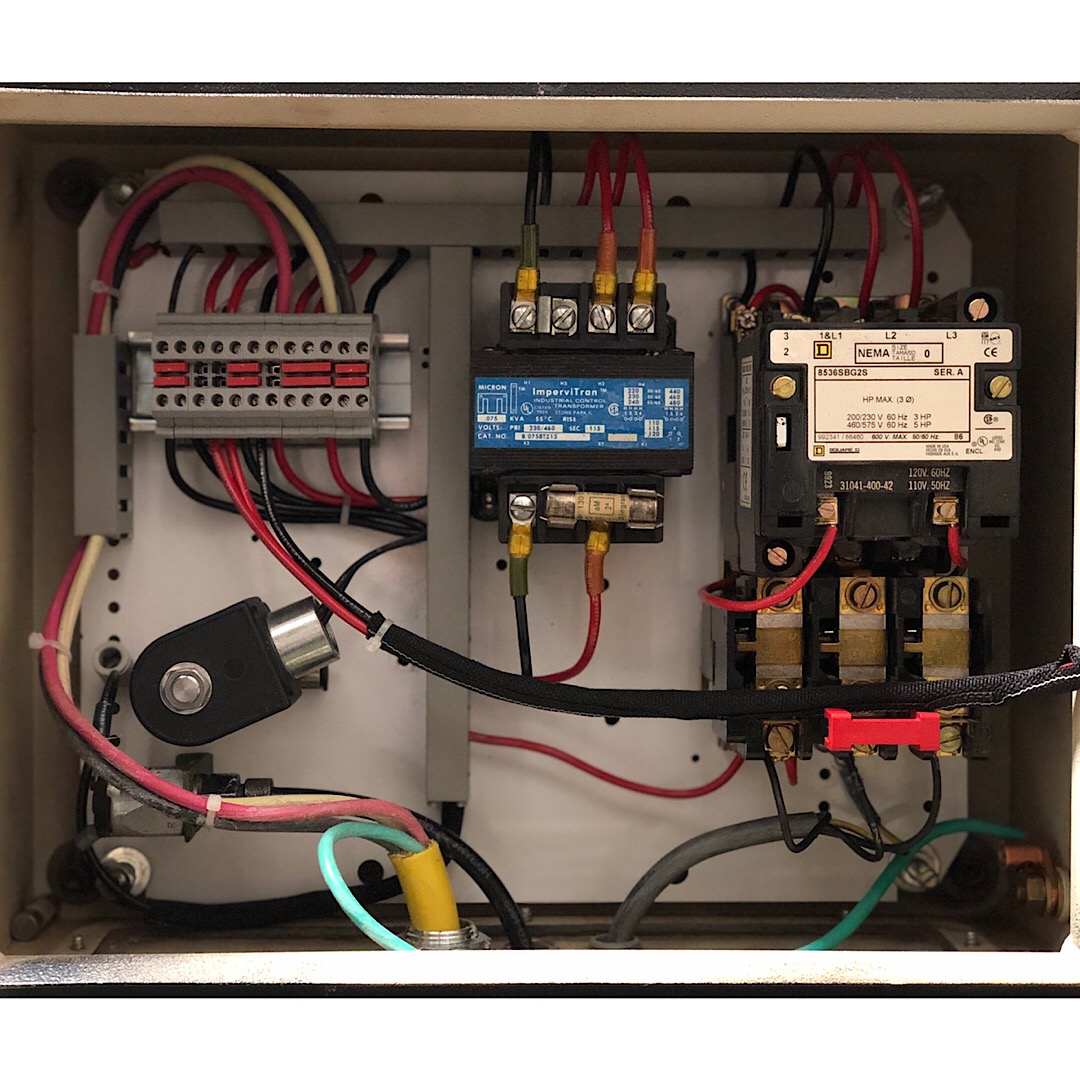
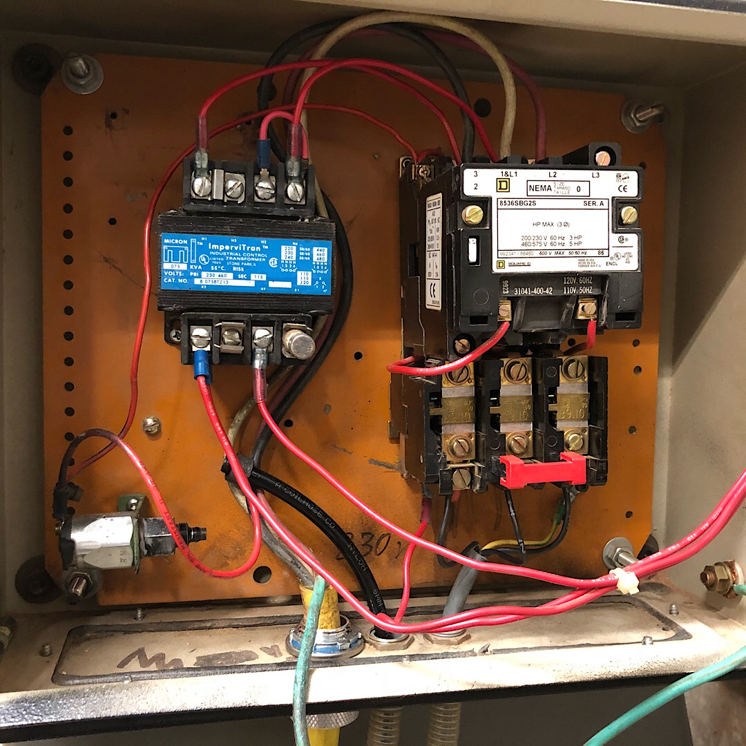
OK, getting this machine up and running soon so that I can process some work through it. I'm running into a snag; I basically duplicated the wiring as it was setup how it arrived, cleaning up the ugly, but not changing anything. However, the previous setup bypassed an air pressure switch, so the machine runs all the time when the lever switch is turned to the forward position. I assumed at the time that if I put the pressure switch back into the loop it would correct this issue, it has not.
I need to ask a couple stupid questions so I can move forward with a few changes to my wiring layout and correct this issue.
I have a step down transformer in the box with 240v going to it and producing 120v
On the 120v side there are four lugs, two are jumped with a fuse, one produces 120v and the last line produces low voltage. I assume this to function like a neutral line, but I'm not sure of the function. It's not marked as a ground and the original setup did not have it wired to the chassis, instead it is wired to one of the lugs on the magnet starter's coil.
This is where my confusion begins. The previous wiring arrangement had the pressure switch tied into the low voltage (neutral?) side of the arrangement, however they had both lugs on one side of the switch, bypassing its function. When these are now reconnected properly, if the switch works, does it then affect anything? I'm starting to think that the switch should be on the 120v side of the wiring, not on the low voltage side.
The pressure switch theoretically interrupts the low voltage side. Should this be setup so that the low voltage connection between transformer and coil is uninterrupted?
- The hot wire from the transformer runs to a lever switch, when the lever switch is operated 'on' it runs to a pilot lamp and to the coil directly.
The machine functions, so I hate to start rerouting things without a clearer understanding of the implications, so I've formed some assumptions and I'm hoping to acquire some information to help me proceed in correcting these issues.
My assumptions so far:
- The pressure switch should be on the 'hot' side of the setup and not the neutral.
- The neutral side of the setup should be continuous, and not interrupted.
I don't believe the pressure switch to be currently functional in any case, so I'm sourcing a replacement. The air going to it is acting properly but seems to have no affect on the function. I believe the pressure switch has failed closed, so it is always on. I can't find any adjustment on it, so my assumption is that it has failed and not that it is out of its proper range.


 Reply With Quote