Page 3 of 3 FirstFirst 123
Results 31 to 42 of 42

Thread: Dust Extraction Duct Routing - High or Low?

  1. #31
    Join Date
    Mar 2015
    Location
    Birmingham, MI
    Posts
    148
    Mike,

    What a phenomenal installation! It looks more like a off the shelf production setup than a homemade 1 off system. I appreciate you sharing your build.

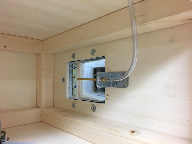
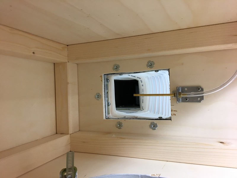
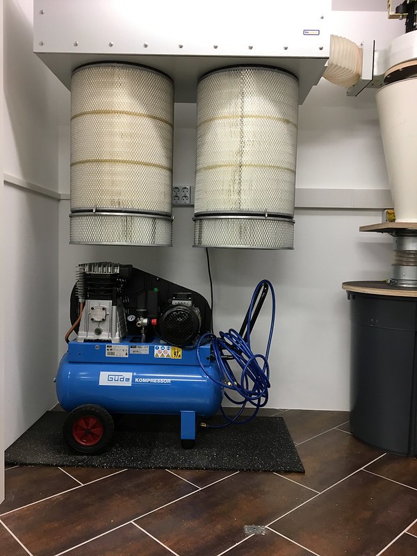
    I am in the process of doing something similar (but not quite the same caliber). Two areas I was interested in was your rectangle hose transition from blower to filter box and how your trash can lid is attached to the can. Specifically how you squared up the hose without damaging it and how you attached/sealed the hose to your connecting blocks.

    Thanks in advance for anything you can share.

    Carl

  2. #32
    Join Date
    May 2017
    Location
    Germany
    Posts
    610
    Thanks, Alan and Carl,

    Here are two interior images showing the mounting of the interface duct and the filter efficiency probe. I used M6 bolts and captive nuts inside the filter box so I could remove the duct without opening the box. The damaged areas along the opening were caused by the drill I used to make the pilot holes for the jigsaw. I should have used a scrap peice of wood as a backing, like I did when I drilled the holse for the captive nuts.


    The opening of the blower assembly was about 155mm X 115mm, which gives a perimeter of 540mm. The closest available flexible ducting with the same or larger perimeter is 180mm duct. The external diameter of the 180mm duct was 185mm, so this gives a perimeter of 581mm.

    The aspect ratio of the height to width of the blower assembly is 0.742, so the dimensions of the modified duct are about 166mm X 123mm. To make the numbers work, I used 166mm X 124mm for the final duct size.

    I then took a half meter section of the 180mm duct, compressed it, and held it in a compressed state with large nylon ties. This gave me a rigid tube to work with while I marked the length for the points to bend. I created a reference line along the length of the tube using a Sharpie marker and a carpenter’s square.

    The reference line was the starting point for the fabric tape measure I wrapped around the tube. I made a series of marks on one end of the tube at the 166mm, 290mm, and 456mm points along the tape measure. I made the same marks on the other end of the tube, then connected the marks using the Sharpie and carpenter’s square.

    Now that I had the bend lines marked along the length of the tube, I cut the nylon ties in order to make forming the rectangle easier. I clamped a long strip of scrap 22mm plywood in a shop vise and fed one end of the 180mm tubing onto it. After aligning a bend line along one corner of the plywood strip, I began pressing the wire of the flexible tubing onto the corner to start the bend. I follwed the line along the tubing until I had to remove it and start from the other end. The plywood was not long enough to accommodate the entire length of tubing, and I didn’t want to make it so long that it would break under the pressure of forming the bend.

    I repeated this process for the four bend lines until I had the start of a rectangle with rounded sides. Once the bends were started on the plywood form, it was easy to continue the bend without the form to 90 degrees and a reasonable small radius. While I finished one corner and moved to the next corner, I also straightened the curved side as best as I could to form a decent rectangle. This process took me about 30 minutes to square the sides of the 180mm tubing.

    The wooden frame to hold the tubing was easy. I used four pieces of scrap wood for each end and glued them together so the tubing was a friction fit ready for silicone sealant and straps to hold it in place. You can see in the image above that the strap is held in place with a 4x12mm screw and washer. The strap was off the shelf at the local hardware store; although, I did have to trim about 10mm from one end of each strap for the short side of the tubing.

    Before screwing the straps in place, I ran a bead of silicon sealant along the inside of the wooden frame, slid (pushed and tugged) the tubing in place, and then snugged the screws down. I have a nice right angle attachment for my drill that made it easy to insert the screws. I filled in the corners between the frame and radius of the tubing with more silicone before letting it cure overnight.

    Here are two images of the interior of the box showing how the Wynn filters are attached. I bought the angle brackets from the hardware store, attached them to the box with screws and nuts, then used the Wynn clips to attach the filters.


    I have not detected any leaks yet from the box, but if I do, I will run a bead of silicone sealant along the seams where the frame and plywood meet.

    I do not have any images of the trash can lid, but I used a piece of 24mm plywood cut larger than the trash can top, a router, and a homemade circle jig for the router to cut a groove in one side of the lid that mates with the trash can top. I had to make several passes for depth and diameter to allow the 27mm gasket (3x9mm strips) to fit in the groove. The gasket section is wider than the trashcan top, so there is a little wiggle room available when putting the lid on the can. I now have a bungee cord to keep the lid snug to the can and to hold the lid to the cyclone filter base when I remove the can to empty the contents.

  3. #33
    Join Date
    Mar 2015
    Location
    Birmingham, MI
    Posts
    148
    Thanks Mike for the response. In addition to the detailed explanation, I also realized that you used the internal Wynn filter clips which I also like.

    Thanks again,

    Carl

  4. #34
    Join Date
    May 2017
    Location
    Germany
    Posts
    610
    Rather than create a new thread, I decided to continue with this thread.

    This weekend I installed digital ammeters in my shop power 3-phase distribution panel. One ammeter is a 3-phase unit that displays only current and scrolls through each phase automatically. I have this connected to the main input feeder so it measures the total shop current. The other ammeters are single-phase and display both voltage and current. I have these connected to the circuit breaker for my DC system. My intent was to baseline my DC system and measure the airflow at each blast gate using the Dwyer 477AV-2 and 166-6 pitot tube. However, my initial power measurements are confusing (to me).

    Here is an image of the ammeters with the DC system off and only the lights to the shop drawing current (on phase L3). In case it isn't clear, for the single-phase ammeters, the number on the top is the voltage and the number on the bottom is the current in Amperes.


    DC_Off by Mike66GE, on Flickr


    I closed all of the blast gates and turned the DC system on. Here is an image of the ammeters with the DC system running, but no airflow through the system. The average current for each phase is about 3.2 Amps.


    DC_Gates_Closed by Mike66GE, on Flickr

    I opened all of the blast gates and turned the DC system on. Here is an image of the ammeters with the DC system running with maximum airflow. The average current for each phase is about 3.2 Amps.


    DC_Gates_Open by Mike66GE, on Flickr


    The difference in the current draw for the DC system with the blast gates open and closed is effectively nothing. I verified that there were no leaks in the system, and with the blast gates closed, I couldn't detect any air flow from the filters.

    I then disconnected the input to the Oneida SDD to see if my 120mm ducting was choking the system even with the gates open. The readings were the same. I put a board over the SDD input to block it off, and the readings didn't change.

    I expected a big difference between the two readings and am not able to explain this. Any suggestions are appreciated.

  5. #35
    Join Date
    Jan 2017
    Location
    Marina del Rey, Ca
    Posts
    1,937
    That's a deluxe setup.
    "Anything seems possible when you don't know what you're doing."

  6. #36
    Join Date
    Feb 2013
    Location
    Tippecanoe County, IN
    Posts
    836
    Mike, when you made the electrical connections to the blower motor did you verify that it was rotating in the right direction? While I have no actual experience with reverse fan rotation in a pressure blower it does seem like that could cause what you are observing.
    Beranek's Law:

    It has been remarked that if one selects his own components, builds his own enclosure, and is convinced he has made a wise choice of design, then his own loudspeaker sounds better to him than does anyone else's loudspeaker. In this case, the frequency response of the loudspeaker seems to play only a minor part in forming a person's opinion.
    L.L. Beranek, Acoustics (McGraw-Hill, New York, 1954), p.208.

  7. #37
    Join Date
    May 2017
    Location
    Germany
    Posts
    610
    Quote Originally Posted by andy bessette View Post
    That's a deluxe setup.
    Thanks, Andy! I bought the 3-phase meter from Mouser Electronics and the three single-phase meters from an eBay vendor in China. All of the meters came with current transformers; although all required some additional work to make them fit in my distribution panel.

    Quote Originally Posted by David L Morse View Post
    Mike, when you made the electrical connections to the blower motor did you verify that it was rotating in the right direction? While I have no actual experience with reverse fan rotation in a pressure blower it does seem like that could cause what you are observing.
    The DC system works well, I think, but there aren't any other systems near me with which to compare it. To remove my nagging doubt, I did reverse L1 and L2 on the blower assembly plug to reverse the motor direction while I had the ducting disconnected from the SDD. Most of the 3-phase cable plugs here have a nice feature that allows the user to rotate the L1 and L2 pins or sockets with a small screwdriver to change the phase rotation. After reversing the rotation, the blower was much noisier, the meter readings were the same, and there was no suction at the SDD inlet. I'm confident I had it turning in the correct direction.

    I made a few quick measurements with the Dwyer 477 and 166-6 along the 3-meter length of ducting that connects to my jointer/planer with only that blast gate open. I started in the center (radius) of the duct and moved towards the edge in 1cm increments. The average velocity was 3,250 ft/min. Without any factoring for turbulence, this is about 396 cubic feet per minute. I have a 2-meter section of 110mm S&D pipe that I was going to use to test at each blast gate, but I think I will find a section of 160mm S&D pipe instead.

  8. #38
    Join Date
    Mar 2003
    Location
    SE PA - Central Bucks County
    Posts
    65,850
    Darn...it looks like you have the Starship Enterprise's control setup there!
    --

    The most expensive tool is the one you buy "cheaply" and often...

  9. #39
    Join Date
    May 2017
    Location
    Germany
    Posts
    610
    Quote Originally Posted by Jim Becker View Post
    Darn...it looks like you have the Starship Enterprise's control setup there!
    Thank you! I was inspired by others here.

  10. #40
    You do not need a big compressor to drive pneumatic nailers. My favorite is a 25 lb Senco that is rated maybe 1/2 hp, has a 1 gallon tank. https://www.amazon.com/Senco-PC1010-...nco+compressor I've used it with my flooring nailer and framing nailer but with those, I have to nail fairly slowly but for small jobs, it is not a problem worth solving by dragging in my bigger compressor. For nailers up through 15 gauge, I can nail as fast as I want. It's also pretty quiet but if you are putting it in a closet, that doesn't matter. Anything this size or bigger will work for nailers.

  11. #41
    Join Date
    May 2017
    Location
    Germany
    Posts
    610
    Quote Originally Posted by Jim Dwight View Post
    You do not need a big compressor to drive pneumatic nailers. My favorite is a 25 lb Senco that is rated maybe 1/2 hp, has a 1 gallon tank. https://www.amazon.com/Senco-PC1010-...nco+compressor I've used it with my flooring nailer and framing nailer but with those, I have to nail fairly slowly but for small jobs, it is not a problem worth solving by dragging in my bigger compressor. For nailers up through 15 gauge, I can nail as fast as I want. It's also pretty quiet but if you are putting it in a closet, that doesn't matter. Anything this size or bigger will work for nailers.
    The compressor I bought was about the same price delivered as the Senco you linked from Amazon. It was on sale and has a 3HP 3-phase motor. It's not the quietest compressor on the block, but the noise is manageable when the closet door is closed and it can't be heard or felt upstairs. It's also light enough that my wife and I can carry it up the stairs when it's time to take it outside and purge the sprinkler system in the winter.


    DC-System-4 by Mike66GE, on Flickr

  12. #42
    Join Date
    Sep 2006
    Location
    Deep South
    Posts
    3,970
    I used a duct system at floor level on my last shop and it worked far better than an overhead system because of the reduction in flex hose length and the straighter galvanized pipe runs. I am using a different collector this time around and I am trying to decide the same thing as you. Some energy (and ultimately cfm) will be lost in lifting dust to a height higher than the cyclone due to the principle of conservation of energy but I don't know how much.

Posting Permissions

  • You may not post new threads
  • You may not post replies
  • You may not post attachments
  • You may not edit your posts
  •