Page 1 of 3 123 LastLast
Results 1 to 15 of 31

Thread: Refurbishing an early wooden Jack Plane.

  1. #1
    Join Date
    Oct 2010
    Location
    Australia
    Posts
    2,534

    Refurbishing an early wooden Jack Plane.

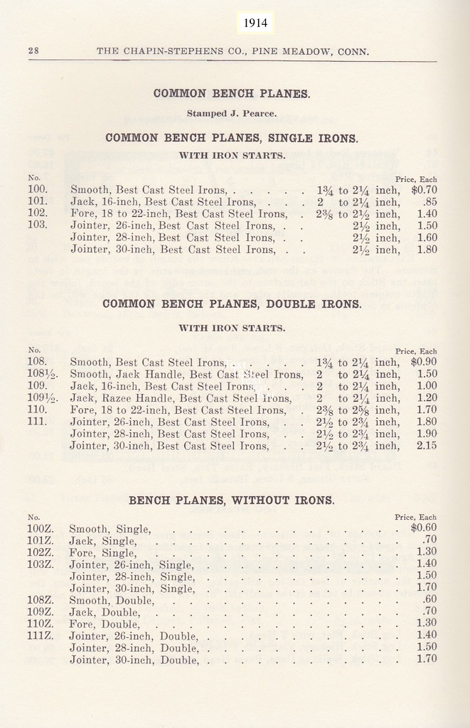
    Received this 16 inch wooden Jack Plane on Saturday morning from an Australian seller. It was manufactured by The Chapin Stephens Co; New York (USA). Both the main stock of the plane and its wedge are both stamped by its previous owner J.LOADER. A special thanks to SMC members Joe Bailey & Don McConnell for providing the information that enabled this planes manufacture date to be narrowed down to 1901-1929. Note: Stanley Co. bought the firm out in 1929, and discontinued the wooden plane making side of this business.


    You will note from the following photo that after unpacking, the wedge is sitting unusually high within its abutments. Details as to why will become more evident further into the post.


    1st up is the condition of the original iron. Its lost around 1 5/16" of its original depth. Likely its been left within 1/2" of usable blade below the softer laminate. The decision was made to put the original iron aside, and replace it with a Nos Isaac Greaves tapered iron of matching width. I will reuse the original cap iron.


    Moving onto the bed on the main stock. Chalking indicated the bed had moved was out of flat.


    The bed was re-worked until the chalking indicated the full surface of the bed was back to being flat. The middle area of the bed was then lightly worked back to leave the critical areas slightly proud.


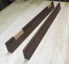
    Moving on to the fit of the wedge within its abutments.

    The wedge was then lightly flat sanded on both of its primary faces. The abutments were also lightly worked back to increase the clearance at the sole from 1/8" to 1/4". That will allow me to later proceed with a partial infill to close up the existing mouth opening. (A full laminate wont be required.) Fine tuning the fit of the wedge was then carried out with the aid of chalking, until contact was made across the full length of the abutments on both sides . 2 additional points to mention. The back of the wedge that allows the upper domed nut of the cap iron to pass unhindered had to be further excavated by 1", to allow the cutting iron to meet flush with the sole. (cap iron was set 1mm behind the irons cutting edge). The ends of the wedge tines also needed trimming back to insure they didn't encroach into the later fit of the 1/4" thick partial laminate. The following photo's show the fit of the wedge after the abutments were fettling in.


    The top of the wedge was shortened by 1/4" to remove the damaged area caused by previous hammering.

    The original finish on the wedge was then cleaned down using denatured alcohol, before an antique mix comprising of red and black powder tint, mixed into a small amount of Danish Oil was then applied. The following photo shows the end result after all the above mentioned had been completed.


    Next on the list of things that need to be done is to re-flattening the sole, and fit a partial laminate to close up the existing mouth opening.

    regards Stewie;
    Last edited by Stewie Simpson; 01-23-2017 at 6:20 AM.

  2. #2
    Join Date
    Oct 2010
    Location
    Australia
    Posts
    2,534
    So the question as to why I had to excavate an additional 1" on the back of the wedge to allow the cutting iron to reach the depth of the planes sole warrants some further thought. The main stock of the plane is original, the wedge is original, the cutting iron is original. The obvious answer is the cap iron is not original to plane, and was replaced sometime before I received this plane. That unlike the normal domed nut height more common found amongst other types of earlier made cap irons, the original cap iron that was original to this plane had the domed nut an inch lower in height. From earlier research received I was made aware that the original securing bolt used by this plane maker was hollow down its centre core, Clearly that was not the only odd practice this early plane maker adopted. A rather odd and strange encounter to come across.

    Stewie;

  3. #3
    Join Date
    Nov 2009
    Location
    Delaplane, VA
    Posts
    117
    Please keep it up, Stewie, I am really enjoying these wooden plane refurb threads. I have a woodie jointer and a smoother I'd like to tune up and you are helping me understand what to examine.

    I also like that you are not afraid to remove a little wood to make an attractive user, as with the wedge here.
    -Dan D.

    Ray's rule for precision:

    Measure with a micrometer, mark with chalk, cut with an axe.

  4. #4
    Join Date
    Mar 2015
    Location
    SE Michigan
    Posts
    3,225
    Thank you Stewie. Really appreciate this post. I have a couple of troublesome woodies and this helps me understand a number of areas I need to check. Look forward to the rest of the project.

  5. #5
    Join Date
    Oct 2010
    Location
    Australia
    Posts
    2,534
    Thanks Dan; appreciate the feedback. I noticed today while working on this plane that there was some slight movement within the mounting of the rear tote. If you look closely at the following photo, there is evidence at the back end where someone has tried to do a quick fix with some hide glue. Its obvious that the repair didn't last long term, so I will need to add to the to do list, remove the rear tote and bond it in place proper with hide glue.

    regards Stewie;

    Last edited by Stewie Simpson; 01-23-2017 at 7:33 AM.

  6. #6
    Join Date
    Oct 2010
    Location
    Australia
    Posts
    2,534
    Quote Originally Posted by Phil Mueller View Post
    Thank you Stewie. Really appreciate this post. I have a couple of troublesome woodies and this helps me understand a number of areas I need to check. Look forward to the rest of the project.
    Thanks Phil; its good to know the information being provided is going to be of some assistance to other members.

    regards Stewie;

  7. #7
    Join Date
    Jun 2012
    Location
    Lubbock, Tx
    Posts
    1,490
    Quote Originally Posted by Dan Duperron View Post
    Please keep it up, Stewie, I am really enjoying these wooden plane refurb threads.
    What he said.

  8. #8
    Join Date
    Jan 2005
    Location
    A suburb of Los Angeles California
    Posts
    644
    Like the others, I'm enjoying this thread and really appreciate the detail. I have a number (20+) woodies (single and double iron) that I couldn't let someone throw away. I'll get to them. I really, really will.
    AKA - "The human termite"

  9. #9
    Join Date
    Oct 2010
    Location
    Australia
    Posts
    2,534
    I decided to bypass the work needed on the sole of the main stock, and focus today on removing the rear tote, and prepping the double iron ready for use.

    Its important to note that the fit on these rear totes is generally favoured to a heel then toe entry. Bearing this in mind, to remove the tote, the toe must exit 1st to allow the heel to follow.

    To soften the hide glue there are a number of options available. Boiling water, hot steam, or using Denatured Alcohol. The last option is what I will be using to remove this tote. 1st is to use a sharp Stanley Knife to score down the glue line to allow the DA to penetrate deeper within the build up of Hide Glue. (I was able to work the knife down 1/4" all the way around the glue line.) The DA was then applied into the glue line using a cheap plastic syringe.


    To loosen the handle further, turn the plane stock upside down and give it a few firm whacks with a wooden mallet. The correct area to strike the sole, is aligned with the totes mortise. (as a reference I have highlighted that area with a permanent marker.)


    Gently tap the totes side to side in both directions, as you continue to reapply the DA into the glue line. When the tote begins to show some significant free movement, turn the sole over again and give it a few more firm whacks with the wooden mallet. With a little perseverance you should be able to fully remove the tote.


    Remove any remaining build up of the old Hide Glue on the mortise and the rear tote, then clean down all areas exposed to the DA, using Mineral Turpentine. Take note of the back bevel on the front of the rear tote within the following photo. That the primary reason why the toe of tote must exit before the heel when being removed.


    Putting the stock of the plane aside for now, its time to focus on prepping the cutting iron. I reshaped the top of the iron using a bench mounted drum sander to resemble that of the original iron. An 0.6mm camber was then applied to the cutting edge using a bench grinder. The cutting edge was then honed to a fine grit of stone, before receiving followed 2 strokes on each side of the cutting edge on a loaded leather strop. To finish up prep work to the iron, a metal darkening solution was then applied above the softer laminate line. Prep work on the cap iron will begin tomorrow, before addresses the sole of the plane.

    Before being prepped. (2nd from left)


    After being prepped.


    Stewie;
    Last edited by Stewie Simpson; 01-24-2017 at 1:53 AM.

  10. #10
    Join Date
    Oct 2010
    Location
    Australia
    Posts
    2,534
    Moving on to fettling the cap iron that was provided with this Jack Plane. The cap iron was 1st cleaned down with DA before being soaked in a bath of Evapo-Rust for 1hr. The front leading edge was then worked on the stone to create a flattened surface. The burr was then worked off the leading edges.


    The critical contact areas between the cap iron and the cutting iron were then cleaned down with DA, before being checked for exact fit using a folded piece of ink transfer paper as the visual medium.


    The transfer marks showed excellent contact was being made. Time to move onto flattening the sole of the Jack Plane.


    The Winding Sticks indicated a slight twist along the soles length. A high area at the heel, and a low area at the toe. Those became the primary focal points to commence dressing back the sole, using a No. 5 Stanley Plane with no camber on the iron.


    The sole was dressed back to the stage where no pencil scribes remained, then the pencil scribes repeated as a double check measure. Chamfering was then applied to outer edges of the sole, before moving on to fine tuning the soles flatness using a flat bed of 220 grit sand paper. The next photo shows the sole of the plane after fine tuning was completed, with the double iron tightened in position.


    The next photo shows a side view of the plane with the unglued rear tote within its mortise. The work I did on reshaping of the top of the iron achieved its desired effect.


    By midday, it was getting to hot to continue any longer. Fitting of the mouth infill is next on the to do list, starting tomorrow.

    Stewie;
    Last edited by Stewie Simpson; 01-24-2017 at 10:37 PM.

  11. #11
    Join Date
    Oct 2010
    Location
    Australia
    Posts
    2,534
    The infill to tighten up the mouth opening has been installed. Progress was delayed while I purchased a new memory card for my digital camera. (32 mb should keep me busy for the next 10 years).

    The piece of timber chosen for the infill has similar characteristics in hardness, grain feature, and hue to that of the main stock of the plane. This was hand dressed down to a constant thickness of 3/8". A wear bevel of 12 degrees was then applied to the front edge of the infill, prior to being cut to length. Note that the grain direction of the infill matches that of the sole of the plane.


    The mortise for the infill was then worked down to depth with a hand router, before gluing the infill in position. Once the glue was dry enough, the infill was then worked on a flat bed of 220 grit with the double iron installed, to bring the infill to a matching height of the soles top surface. 2 coats of powder tinted Danish Oil was then applied to the soles surface to increase its general wear resistance.


    Next on the list is to prep the rear tote and its mortise depth in preparation for the hide glue.

    Stewie.
    Last edited by Stewie Simpson; 01-27-2017 at 1:37 AM.

  12. #12
    Count me among those who appreciate this sort of thing.

    By the way, the photography is outstanding.

  13. #13
    Join Date
    Oct 2010
    Location
    Australia
    Posts
    2,534
    That's good to hear Joe. I was beginning to think this thread had a low threshold of interest. Thank you again for your help in identifying this Jack Planes date of manufacture.

    regards Stewie Simpson.

  14. #14
    Join Date
    Jan 2007
    Location
    Michiana
    Posts
    3,072
    Quote Originally Posted by Joe Bailey View Post
    Count me among those who appreciate this sort of thing.

    By the way, the photography is outstanding.
    I'll second both sentiments. I've always found the restoration process fascinating.
    Sharp solves all manner of problems.

  15. #15
    Join Date
    Nov 2009
    Location
    Delaplane, VA
    Posts
    117
    Hi Stewie,

    Your post on removing the tote got me thinking about strike buttons. Can they be removed the same way?

    I have a nice woodie razee-style jointer that some idiot took a random-orbit sander to, I guess to 'clean it up'. The patina is trashed, about 2/3 gone. I'm thinking it would easily clean up with a light shaving off each face, but on the top that button would be in the way.
    -Dan D.

    Ray's rule for precision:

    Measure with a micrometer, mark with chalk, cut with an axe.

Posting Permissions

  • You may not post new threads
  • You may not post replies
  • You may not post attachments
  • You may not edit your posts
  •