Page 3 of 5 FirstFirst 12345 LastLast
Results 31 to 45 of 70

Thread: CastCNC Alum carriages for my machine coming in 2011

  1. #31
    Join Date
    Oct 2006
    Location
    Bloomington, IL
    Posts
    6,009
    Thankyou Carol for letting me know you are reading it and like it. In these stages a lot of the pictures are boring to some - until they decide to do something similar and then you wish there were more pictures (at least I did). Thank you though very much for the comment.

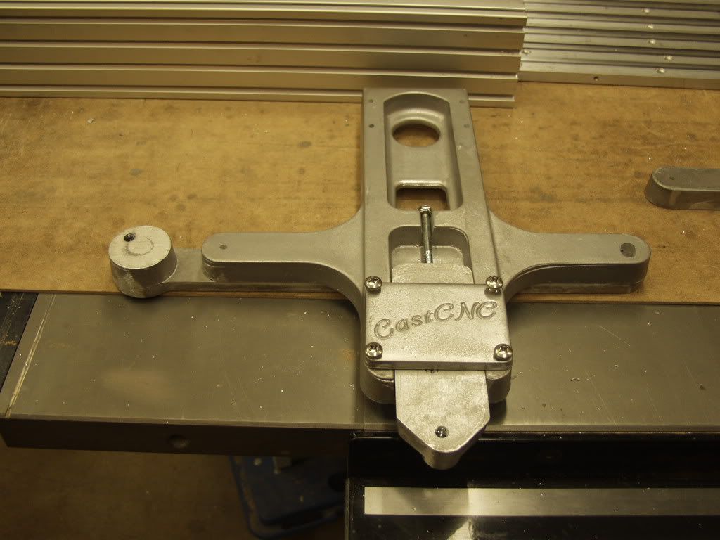
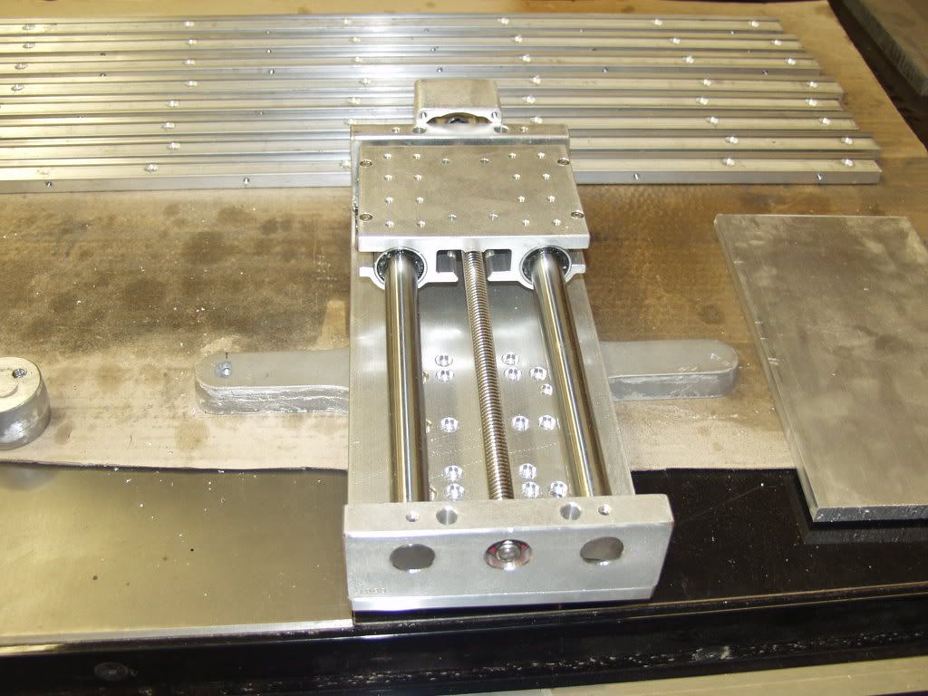
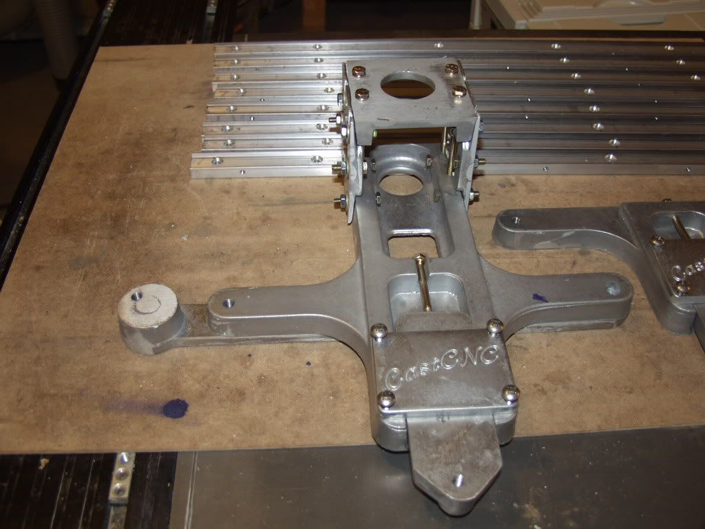
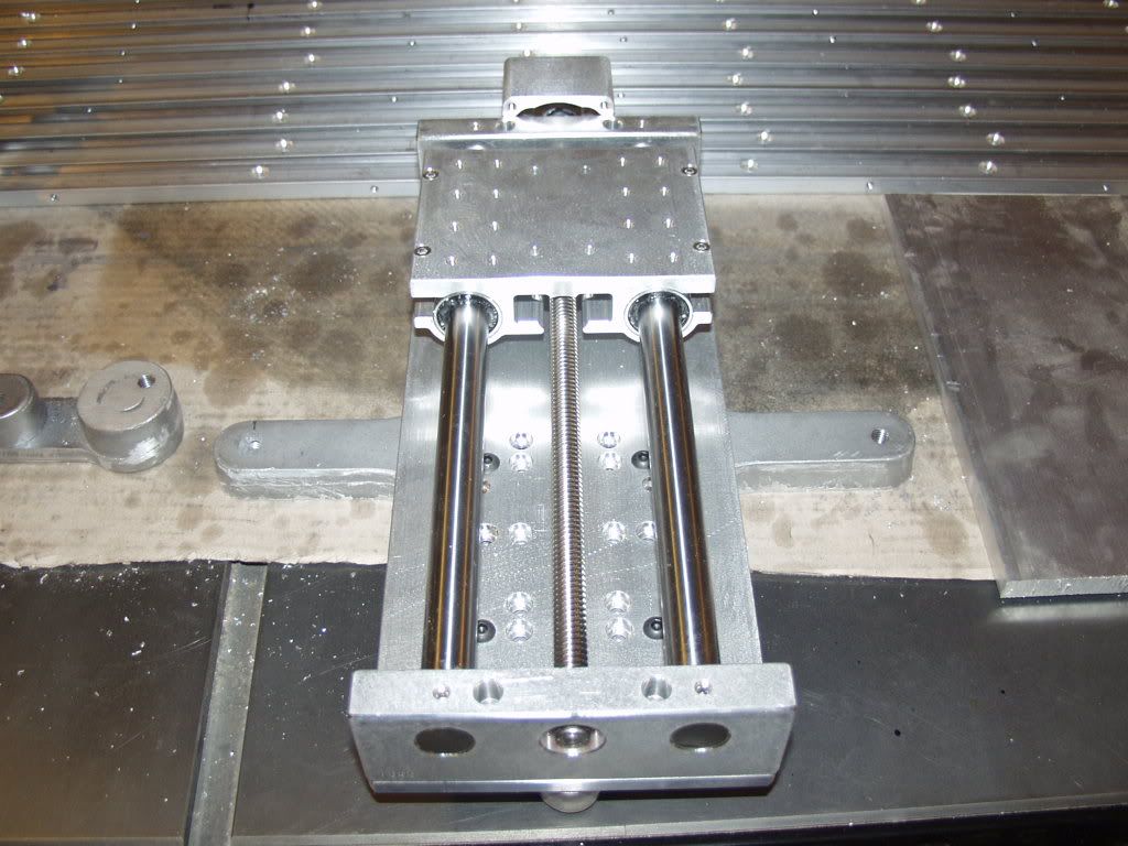
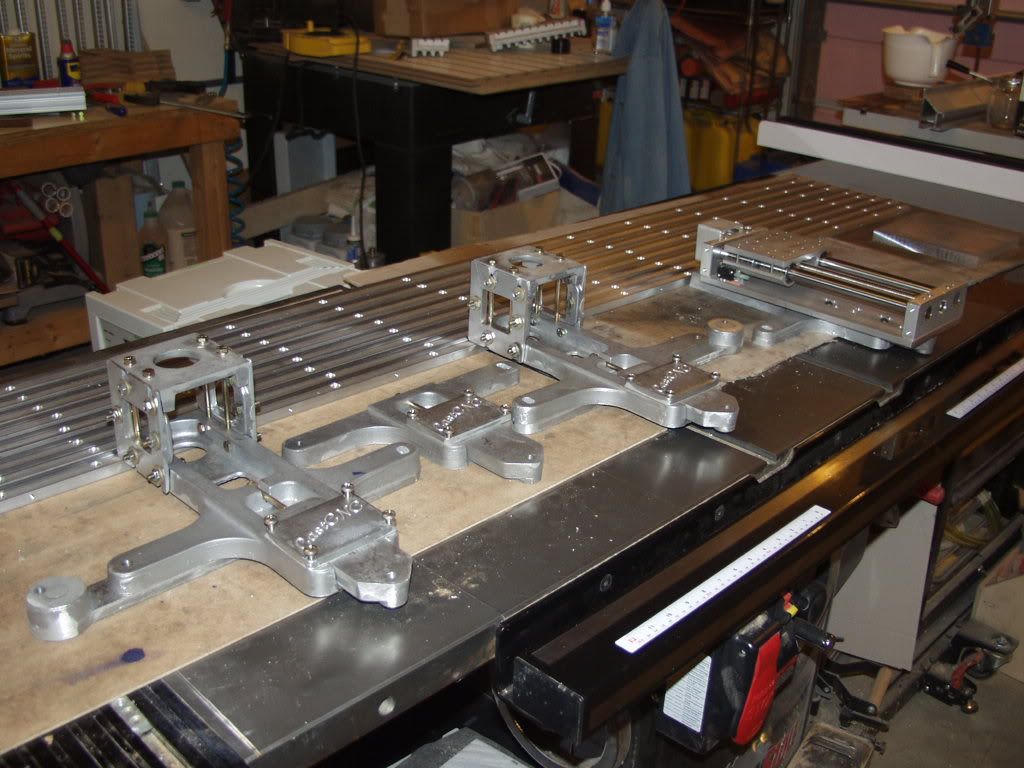
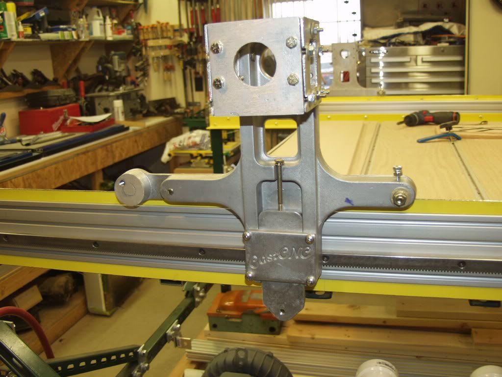
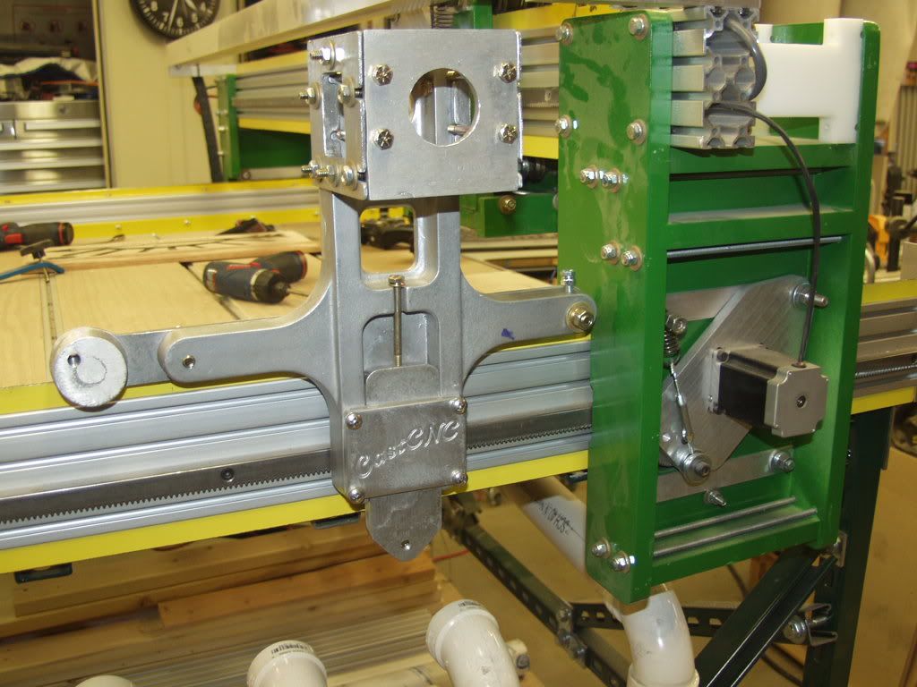
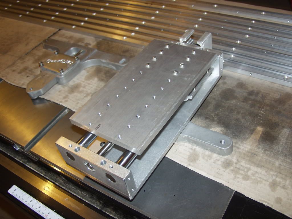
    Tonights work was tapping teh holes in teh face and attaching the cast cnc covers and attaching the Linear Z from K2CNC the X front truck. I will post pictures tomorrow some time.

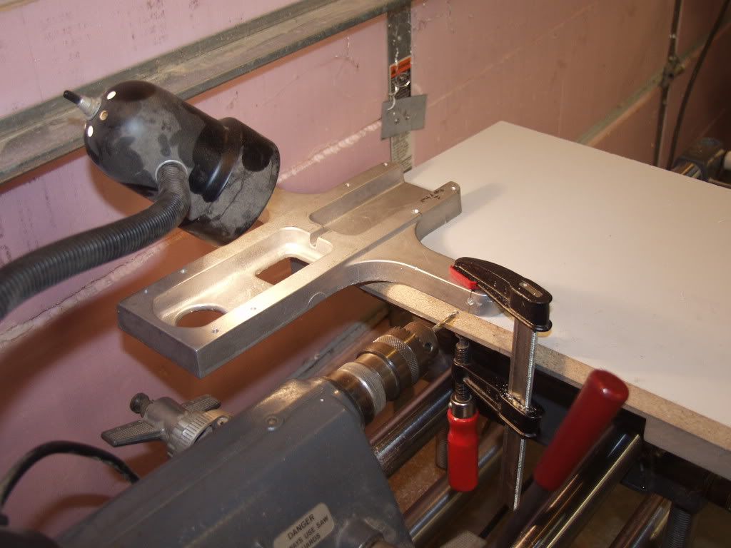
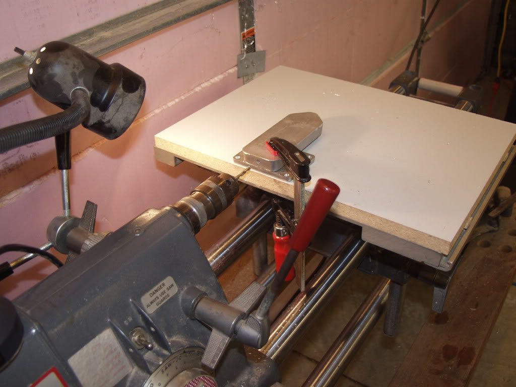
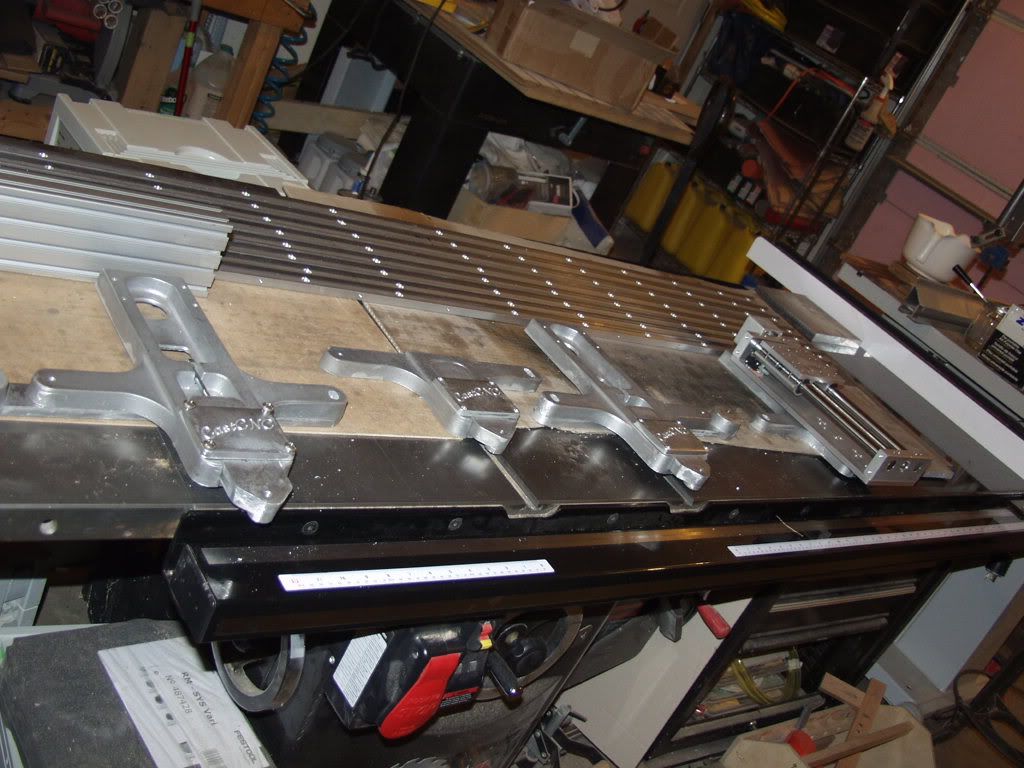
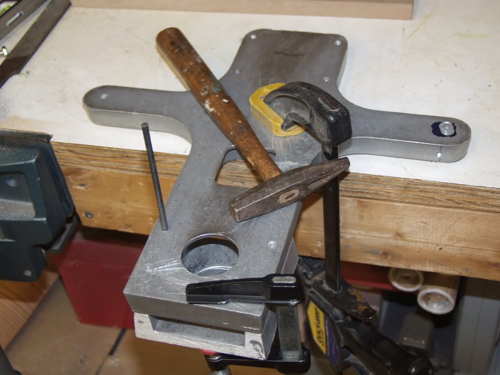
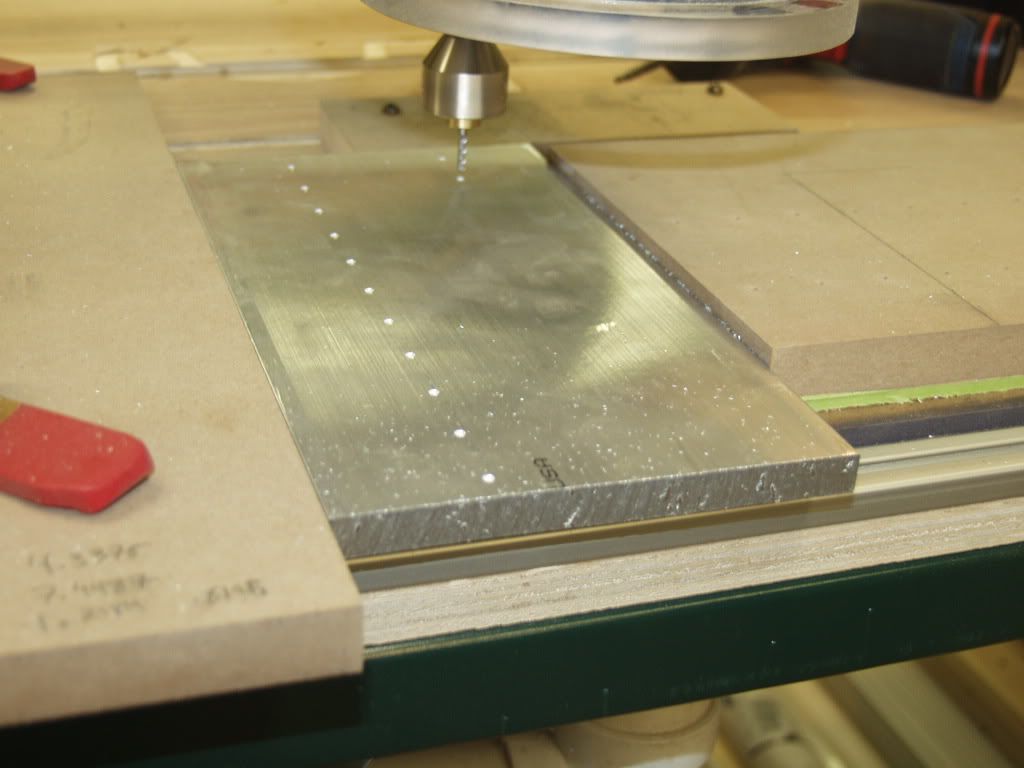
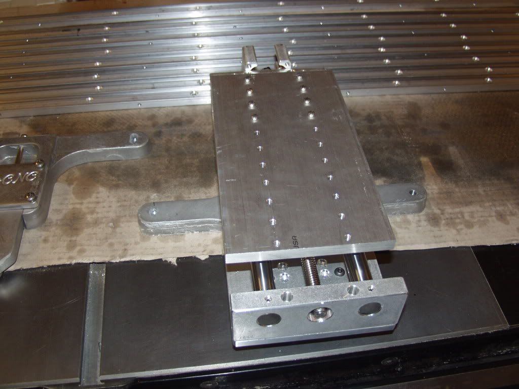
    Also started marking up the edge of the X back truck. Tomorrow I will dust off the old Mark V Shopsmith and use the horizontal boring feature of that setup to drill the edges.
    Glad its my shop I am responsible for - I only have to make me happy.

  2. #32
    Join Date
    Jun 2005
    Location
    Pahrump, NV
    Posts
    119
    You're welcome, Mike. I do have a glossary type question. I understand the gantry to be the carriage that traverses the Y axis, carrying the Z axis which traverses the X axis. What is the X truck, let alone the back and the front of it? If it is the horizontal member between the two vertical members of the gantry, and the front is where the Z axis is mounted, then I will have another question or two. Thanks.
    Carol in NV

  3. #33
    Join Date
    Oct 2006
    Location
    Bloomington, IL
    Posts
    6,009
    X truck (X carriage) carries my bolt on Z axis. X truck front is a cross shaped piece that receives the bolt on Z. The X truck back is the T shaped portion of that X carriage.
    Glad its my shop I am responsible for - I only have to make me happy.

  4. #34
    Join Date
    Jun 2005
    Location
    Pahrump, NV
    Posts
    119
    OK. In the first picture of your first post, the red assembly is the X truck? I see a cross shape there for the bolt-on z axis, and the rear T-shape. What I am kicking around in my head, is the parallel 8020 horizontal pieces of the gantry being separated to accommodate the Z axis between them. That considerably widens the gantry, but also provides a greater degree of rigidity. The Z truck(?) would ride the X carriage like the gantry rides the Y carriage. I hope my terminology is correct. Comments?
    Carol in NV

  5. #35
    Join Date
    Oct 2006
    Location
    Bloomington, IL
    Posts
    6,009


    Here is a picture from the edrawing showing the X rack and pinion portion of the drive mechanism of that truck. It would have to be changed to do what you are asking. Notably you could drive it like one of the Y trucks but that would be custom and require additional cast parts. What are you trying to make more ridgid - the Z or the gantry? The seperation already in the design of the two 8020s in teh gantry should help with that along with the lower X brace on the 8020s. The Z is VERY ridgid.
    Glad its my shop I am responsible for - I only have to make me happy.

  6. #36
    Join Date
    Jun 2005
    Location
    Pahrump, NV
    Posts
    119
    Very cool drawing! Just doodling in my mind. No real commitment to a particular design that has not already been devised and for which plans are readily available. Thanks for your explanations, Mike. The pictures and drawings are very, very helpful for this visual learner.
    Carol in NV

  7. #37
    Join Date
    Oct 2006
    Location
    Bloomington, IL
    Posts
    6,009
    Todays accomplishments: Getting closer.

    Horizontal bored, using my Mark V Shopsmith, the aduster holes and the rear truck for the lower bearing slide bolt and all the lower bearing plates. Tapped them as well and drilled and tapped them for the bearing. Drilled and tapped the pinion gear arms. Went with the alternate hole location due to V-rail install and provides for nema 34 upgrade potential in the future. Made a jig on the cnc router to mark that hole (then used a center punch) and the holes for the bearings in the lower bearing slides, Jig was cut out of MDF.


    Glad its my shop I am responsible for - I only have to make me happy.

  8. #38
    Join Date
    Jun 2005
    Location
    Pahrump, NV
    Posts
    119
    I really like your build. Tell me more about the edrawing of the x truck back. I am assuming there are more edrawings. Are these part of someone's plan? Or are they from CastCNC? I know, join Joe's forum. Gotta wait for the next payday for that. Thanks for being patient with me. You have been very helpful and encouraging. Sometimes for visual learners like myself, it is hard to find pictures so I can visualize the project and thus determine the process. I'd rather make informed decisions!
    Carol in NV

  9. #39
    Join Date
    Feb 2007
    Location
    South Dakota
    Posts
    1,632
    Man I wish I was building one of these. I would really like to get started but I think it wont happen this year. Thanks for posting.
    The Plane Anarchist

  10. #40
    Join Date
    Oct 2006
    Location
    Bloomington, IL
    Posts
    6,009
    So I talked with Harry about teh drawings and he now made them available on the cast website. http://www.castcnc.com/box.html Edrawings software link is there to. Should show you everything you need. I use them to figure out which bolt goes where

    I decided to focus on the truck boxes today (they mount the 8020 x gantry) and the 3/8 through holes for the bearings and tapping for them on the trucks. Got that all done. I used a piece of cut off 8020 to mark up the mount holes for the side plates of the boxes to ensure it will all fit. Also the shopsmith came in super handy again drilling the edges of the cross trucks and the front box pieces. Only things left are to drill and tap for the saddle which will happen when I begin assembly and then drill and mount the X pinon motor plate. Also need to drill the X cross braces which I will do tomorrow. Here are todays pictures.


    Glad its my shop I am responsible for - I only have to make me happy.

  11. #41
    Join Date
    Oct 2006
    Location
    Bloomington, IL
    Posts
    6,009
    Borrowed an extra set of V bearings today and put the Y trucks on the existing rail. Man I love the solid tightening bolt action slide of the lower bearing plate! Michael Simpson Virginia build that style design into your next machine!! It is awesome.


    Here is the before Y carriages in John Deere green MDF and after in rough cast aluminum.

    Glad its my shop I am responsible for - I only have to make me happy.

  12. #42
    Join Date
    Oct 2006
    Location
    Bloomington, IL
    Posts
    6,009
    Tonight I drew up a 6"X11"X1/2" Z plate (the size of the piece of alum I had) in Vcarve and ysed the router to mark the holes. I then drilled through for the mounting holes to the Z and drilled and tapped the holes for mounting the K2 router mounts. Worked perfectly.


    Glad its my shop I am responsible for - I only have to make me happy.

  13. #43
    Join Date
    Jun 2005
    Location
    Pahrump, NV
    Posts
    119
    You're using a CNC to build your CNC! Isn't that cheating?

    BTW, I got the edrawings. Thanks. That helps my visual brain a lot!
    Carol in NV

  14. #44
    Join Date
    Oct 2006
    Location
    Bloomington, IL
    Posts
    6,009
    T-minus 16 hours until disassembly. This newest upgrade chapter came together Sunday - I checked out my buddies welded base (based on Joe's specs) and I ordered him a new one and he is delivering teh one he has as he will not be assembling his machine till June at least. So, A new welded base arrives 3pm Thursday so tomorrow she comes apart. Having this idea of bolting some unistrut to the welded base to use as mounts for my controller box, PC, and Vacuum manifold. Tonight the MDF carriages cut their last sign on my machine. Carol, you want to buy some MDF and HDPE Joes parts?? Like JD Green?
    Glad its my shop I am responsible for - I only have to make me happy.

  15. #45
    Join Date
    Oct 2006
    Location
    Bloomington, IL
    Posts
    6,009
    T minus 16 hours until disassembly. A New welded base arrives 3pm Thursday so tomorrow she comes apart. A buddy who is also building a Joes R&P machine had a base welded up. I checked it out Sunday and I order him a new one and he is delivering his to my shop so I will have one in time for my upgrade. It is based on Joes welded base specs with the addition of leveling feet (1" all thread on 4" Plate. I am Having this idea of bolting some unistrut to the welded base to use as mounts for my controller box, PC, and Vacuum manifold. Tonight the MDF carriages cut their last sign on my machine.

    Carol you want to buy some R&P MDF carriages, My Vrailed Z, and the HDPE parts? Like JD Green?
    Glad its my shop I am responsible for - I only have to make me happy.

Posting Permissions

  • You may not post new threads
  • You may not post replies
  • You may not post attachments
  • You may not edit your posts
  •