Page 1 of 3 123 LastLast
Results 1 to 15 of 41

Thread: New Woodworking Bench (Parts I & II of II)

  1. #1
    Join Date
    Feb 2003
    Location
    Washington, NC
    Posts
    2,387

    New Woodworking Bench (Parts I & II of II)

    Way back in Sept '07 after completing new extension and outfeed tables for my tablesaw, I said that my next project was going to be a relatively traditional woodworking bench based on a design by Lon Schleining which was first published in FWW a few years ago (see the copy on my extension table) . However there was always something with higher priority, and I never got around to it.


    Then, last December, while working on my second adjustable height assembly table (for a magazine article), I wondered if the adjustable legs I designed and built for those tables could be adapted to a woodworking bench such that the bench would be strong and stable.

    I broached the subject to some friends and posted a few SketchUp drawings of the leg design. However the location of the stretchers on the initial design would likely have make it difficult or impossible to lift the top to adjust the bench height.


    I subsequently changed the location of the stretchers from the fixed legs to the adjustable legs.

    Since I already had an indexing jig set up to cut the leg notches for the assembly table legs, I decided to make the woodworking bench legs at the same time, using some beech I had sitting around the shop- that was over 9 months ago. This Spring I picked up a 30" x 72" x 2.75" maple top and some pieces for the aprons from Bally Block, then on a trip to Raleigh last month I picked up a few more pieces of beech for the base and more maple for the vise jaws at Klingspor. So finally, almost two years after having made the decision and over 9 months after actually cutting the first pieces, I had all the materials (and made the time) to actually start working on the new bench. I didn't take any in-progress shots, but here are some pics of the nearly completed adjustable height trestle base with top installed. I still need to add the maple aprons, 3 vises (QR front vise, sliding tail vise, Veritas twin screw tail vise), and bench dog holes.

    Revised SketchUp drawing. (minus ratchet arms and release cords). Unlike my assembly table legs which stay together by sliding dovetails, these legs mate with a "V" and "V groove". The ratchet arms draw the leg halves together and keep the matching "V" profiles solidly mated.


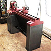
    The unfinished top is just resting on the trestle base which is in its lowest (30") position. It is adjustable in 1" increments.


    End view showing top and bottom draw bored tenon pins on legs and wedged through tenons on stretchers.


    Close-up shot of ratchet pawl arms (minus release cable) and stretcher tenons.


    End view, one notch below full height (43").


    The adjustable height mechanism works very, very well (as good or better than the ones on my assembly tables). The bench is very sturdy, stable, and does not rack. While heavy, it lifts fairly easily -obviously one end at a time.

    Before I continue, here are some stats-

    Design:
    • A mix of elements from Lon Schleining's "The Best of Old and New" bench from his book and Fine Woodworking article. Elements include his thumbnail profiles on the feet and jaw faces, etc. and my own designs including the adjustable height trestle base. The adjustable trestle base is a new twist on my assembly table adjustable height legs which will be the subject of a forthcoming article in Dec/Jan issue of American Woodworker.


    Materials:

    • Top, aprons, vise jaws- hard Maple

    • * Adjustable trestle base- American Beech.


    Construction:

    • Trestle base- mortise & tenon and Titebond III
    • A mix of pinned-blind and wedged-through M&T joints
    • Aprons (and sliding tail vise) joined with hand-cut, half-blind dovetails - 6 sets!
    • Long side aprons attached to the top with glue only (long grain to long grain)
    • End aprons, to allow for seasonal changes in the cross-grain direction, are held in place with threaded rod, nuts, and barrel nuts. No through bolts or plugs are visible on the end vise face or free end aprons of the bench. Nuts are accessible from underneath to allow tightening.


    Dimensions:
    • Top: (not incl. vises): 33-1/2" wide x 74" long x 2-1/2" thick- Yes, it is BIG!
    • Aprons: 1-3/4" thick x 5" high
    • Height: adjustable: 30-1/2" to 43-1/2"
    • Weight: TBD, but HEAVY!!!


    Vises:
    • Lee Valley twin screw full width tail vise (20" between lead screws) (3" thick jaw)
    • Quick release front vise (3" thick jaw)
    • Sliding tail vise (w/o shoulder)


    (all vise hardware was free, courtesy of the Woodcraft Top Shop contest gift certificate )

    Aprons and vises installed:


    On one end is a Lee Valley/Veritas Twin Screw, full width, tail vise. It was a custom installation. Rather than surface mount the vise and add the chain housing to the back of the 3" thick vise jaw like the typical installation in the first picture below, I routed a recess for the flanges, sprockets, and chain and made a new, low profile cover.


    Part II below
    Last edited by Alan Schaffter; 09-11-2009 at 1:25 AM.

  2. #2
    Join Date
    Feb 2003
    Location
    Washington, NC
    Posts
    2,387

    New Woodworking Bench (Part II of II)

    One detail I haven't shown was how I attached the cross-grain aprons to the bench. Since they are cross grain you can't use glue without the danger of seasonal movement causing problems. Lon Schleining in his FWW bench article (which was my inspiration for this bench) and the instructions that came with my Lee Valley vise used a method similar to that used to attach breadboard ends. Like those, I milled a tenon on the end of bench and a slot on the back of the apron. They recommended attaching the apron with machine bolts in counterbores and barrel nuts buried in the table. Then they plugged the bolt head holes. I had two problems with that- appearance and the inability to tighten the bolts and snug up the apron at a later date. My solution was to bury barrel nuts in the apron, use 1/4-20 all-thread rod in a 3/8" hole (to allow movement), and pull it all tight with a nut and washer in a pocket in the underside of the table. It worked great!:

    No visible hole plugs covering bolt heads:


    A view under the table. The hole on the left is for the barrel nut. A nut and washer is installed on the all thread rod in the pocket at right. I drilled three close holes and chiseled away the remaining wood to make the pockets. If I had a small ratcheting box wrench I could have made the pockets smaller. I can easily pull the aprons very tight this way:


    I am using 3/4" round Lee Valley Bench Dogs and Pups. When I laid out the locations for my dog holes I was very careful to avoid the locations of vise hardware and bench structure. I made a drill guide on my drill press and used it to keep and electric hand drill perpendicular while drilling holes in the top of the table and the aprons. I drilled the holes in the vise jaws on the drill press. Once I had one row completed I was able to use my Gramercy holdfasts to help clamp the guide:


    After some serious planing, scraping and sanding, the bench was finished with a 60/40 mix of mineral spirits and marine varnish. I will probably knock down the gloss of the top with steel wool or a Scotchbrite pad, then give it a few coats of wax. The bench is at its lowest height (30") here:


    And its highest (43") here:


    The quick release front vise (r.) and sliding tail vise (l.). I used my lathe to turn the vise handles out of scrap maple. The end knobs came from the local Michaels craft store.


    The adjustable legs are a variation of those I designed for my assembly table. I added a small pedal to release the ratchet pawls when I lower the table. I am not completely satisfied with the pedal arrangement and may change it. The bench is heavy, but changing height is not too bad. It is something that I won't be doing often once I find a comfortable working height, but if I need it, I have that capability.


    The finishing touch is a label Rob Lee of Lee Valley graciously sent me along with some cork vise facing. I put the label on the chain cover I made for my custom Lee Valley/Veritas Twin Screw Vise installation. Thanks Rob!

    Last edited by Alan Schaffter; 09-11-2009 at 1:30 AM.

  3. #3
    Join Date
    Nov 2006
    Location
    Trussville, AL
    Posts
    3,589
    Prepare to be shamelessly copied. I love the idea for attaching the aprons!

  4. #4
    Join Date
    Dec 2005
    Location
    Fontucky, California
    Posts
    430

    Benc

    Very nice!!!! I love home made benches. Always fun projects to build!!!

    I'm curious as to why you wanted adjustable height. Also, that seems to be quite a range of adjustability. Do you find that you actually change the height all that much and do you use the full range?

    I tend to like my benches higher than most so that's how I built the last few. I've seen the adjustable ones that some vendors sell but always wondered if I'd really ever change the height, so I'm curious to hear if you do and how often.

    Again, very nicely done!!!!!

    Regards,

    John

  5. #5
    Join Date
    Feb 2003
    Location
    Washington, NC
    Posts
    2,387
    Quote Originally Posted by John Harden View Post
    Very nice!!!! I love home made benches. Always fun projects to build!!!

    I'm curious as to why you wanted adjustable height. Also, that seems to be quite a range of adjustability. Do you find that you actually change the height all that much and do you use the full range?

    I tend to like my benches higher than most so that's how I built the last few. I've seen the adjustable ones that some vendors sell but always wondered if I'd really ever change the height, so I'm curious to hear if you do and how often.

    Again, very nicely done!!!!!

    Regards,

    John
    Thanks. I could not decide on an optimum height and knew if I picked one I would be stuck with it unless I built a completely new base. I had already designed a version of these legs for an assembly table. I change the height of that all the time- from low sitting height, to lean-over working height, and full up to standing height. The WW bench is too new to tell how much I will use the adjustable height, but as I said, if I need the capability, I have it.

  6. #6
    (hands clapping)

    Wonderful bench and wonderful documentation.
    Thanks for inspiring!

  7. #7
    Join Date
    Dec 2005
    Location
    Fontucky, California
    Posts
    430

    Height

    Quote Originally Posted by Alan Schaffter View Post
    Thanks. I could not decide on an optimum height and knew if I picked one I would be stuck with it unless I built a completely new base. I had already designed a version of these legs for an assembly table. I change the height of that all the time- from low sitting height, to lean-over working height, and full up to standing height. The WW bench is too new to tell how much I will use the adjustable height, but as I said, if I need the capability, I have it.
    I hear you there. A few times I have wanted my bench a bit lower or higher, so I'm curious to see how often you change the height down the road.

    Completely agree with you on an adjustable height assembly bench. About half the time I want it about waist high and the other half I want it 12-18" high.

    Regards,

    John

  8. #8
    Brilliant. Simple and brilliant.

  9. #9
    Ditto what Cliff said. I am very impressed.
    Hello, My name is John and I am a toolaholic

  10. #10
    Join Date
    Jun 2009
    Location
    Western Maryland
    Posts
    5,548
    I am speechless. How in the world could you ever USE that? I wouldn't even set a beer on that without a coaster... unbelievable.
    I drink, therefore I am.

  11. #11
    Join Date
    Dec 2005
    Location
    Fontucky, California
    Posts
    430

    Clever design of the legs

    At first glance, I'd think that it would tend to rack quite a bit back and forth under pressure, particularly since the load is on the narrow inner legs.

    However, after looking at it closer, I see how you designed the inner legs so they nest inside the outer ones with the arrow head shaped profile.

    I'm gonna guess that profile, coupled with the design of the bars/bracket that meshes with the teeth forces the inner legs out towards the outer ones and eliminates any racking.

    Are my guesses correct? If so, very clever design. I'm impressed!!!!

    Regards,

    John

  12. #12
    Join Date
    Nov 2007
    Location
    Colonial Heights, Virginia
    Posts
    200
    That is absolutely awesome! Great design and excellent execution. Thanks for documenting it so well.
    Gary

    "It is neither wealth nor splendor, but tranquility and occupation which give happiness. " Thomas Jefferson

  13. #13
    Join Date
    Aug 2004
    Location
    Baltimore, Md
    Posts
    1,785
    Love it ! If I didn't have so many projects in the hopper now I would certainly be working towards something like this !
    "The element of competition has never worried me, because from the start, I suppose I realized wood contains so much inspiration and beauty and rhythm that if used properly it would result in an individual and unique object." - James Krenov


    What you do speaks so loud, I cannot hear what you say. -R. W. Emerson

  14. #14
    Join Date
    Feb 2003
    Location
    Washington, NC
    Posts
    2,387
    Quote Originally Posted by John Harden View Post
    At first glance, I'd think that it would tend to rack quite a bit back and forth under pressure, particularly since the load is on the narrow inner legs.

    However, after looking at it closer, I see how you designed the inner legs so they nest inside the outer ones with the arrow head shaped profile.

    I'm gonna guess that profile, coupled with the design of the bars/bracket that meshes with the teeth forces the inner legs out towards the outer ones and eliminates any racking.

    Are my guesses correct? If so, very clever design. I'm impressed!!!!

    Regards,

    John
    Correct. You nailed it! The legs have mating "V" male and female shapes with the tip of the male "V" flattened on the inner (upper) leg so it won't bottom out and nests tightly. The leg attachment to the base is tight and solid, but, the lower legs and the base form a "U" which will flex just enough that they can be pulled tight against the upper legs by the weight and angle of the ratchet arms.
    Last edited by Alan Schaffter; 09-10-2009 at 11:26 PM.

  15. #15
    This is an awesome workbench design and it is beautifully executed. Except for one thing. The little "foot pedal" thing with the string and wires? That's gotta go. It just does not measure up to the rest of the project and detracts from the whole. Sorry... I don't mean to belittle your effort which is far beyond anything I have ever attempted for my own shop. And it's a little thing really. Surely you can come up with something a bit more elegant? Other than that, I am ....well... shut my mouth!
    David DeCristoforo

Posting Permissions

  • You may not post new threads
  • You may not post replies
  • You may not post attachments
  • You may not edit your posts
  •