Page 1 of 4 1234 LastLast
Results 1 to 15 of 60

Thread: Infill Shoulder Plane Rebuild

  1. #1
    Join Date
    Jan 2008
    Location
    San Antonio, Republic of Texas
    Posts
    434

    Infill Shoulder Plane Rebuild

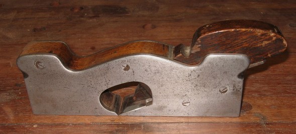
    I recently acquired an infill shoulder plane body for about $27 that had been damaged in a fire.

    IMG_1813.jpg

    I plan to restore the plane and make a new blade for it out of O1 tool steel. So I've been doing some research and looking at pictures of other infill shoulder planes and I've got some questions, I hope can be answered.

    This is the back of the plane:

    IMG_1814.jpg

    In pictures of other infill shoulder planes I've seen, there's a screw of some type that goes into this hole. What is this screw used for?

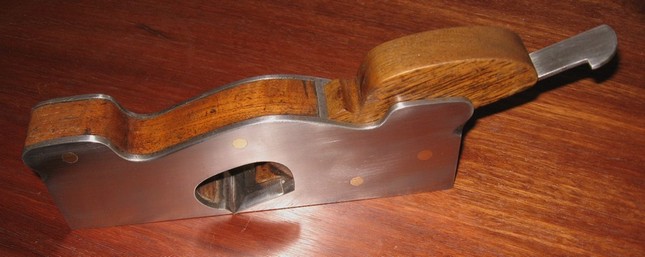
    At the front of the plane there is this cross bar:

    IMG_1815.jpg

    I know I'll need to cut that out and clean out the holes in the sides and then fit my new wood infill. When I replace the rod, I'm thinking I may use brass as it should be easier to work. So, what's the trick to getting a rod in there flush with the sides and so it won't just slide out again?

  2. #2
    Join Date
    Sep 2008
    Location
    Raleigh, NC
    Posts
    2,854
    What you have strongly looks like a Norris #7. To answer your questions:

    The hole in the back is for a screw used as a strike button. You whack that with a hammer and it will loosen the wedge and retract the blade. The type of screw is called a "cheese head", and I think it's unlikely you'll be able to find a new replacement. I've looked and looked and looked, and the only cheese-heads I've found for sale as new screws are metric. I've not gauged the threads in the hole on one of these, but I'm pretty sure that it would be Imperial (i.e. "English") threads.

    The closest thing one can easily buy now is a so-called fillister head screw. These look a lot like cheese-head screws, except that the top is very slightly domed instead of being absolutely flat. These also seem to be only offered in metric threads, so you may have to buy a few that are too big for the hole and drill it out and tap it.

    Regarding the bar you're seeing on the front - that's a pin that was placed through the sidewalls of the plane and through the front infill to hold it in place. These were peened into slightly flared holes in the side wall so that they will lock. You can pretty easily do the same - cut the rod out of the plane body, cut and fit your infill, then drill through both sidewalls and the infill and slightly flare the holes (so that they're bigger on the outside of the sidewalls). Then place a piece of mild steel rod through the holes that's a bit too long, and lightly tap on the ends to peen the steel into the holes. Cut the excess off, and lap the sides to remove the projection.

    By the way - If you'd like to just buy a blade for this plane rather than make your own, you can get repros from The Best Things. Their shoulder plane blades for infills fit very well and are the proper thickness.

  3. #3
    Join Date
    Jan 2008
    Location
    San Antonio, Republic of Texas
    Posts
    434
    Quote Originally Posted by David Keller NC View Post
    What you have strongly looks like a Norris #7.
    It could be. On the very front there is an oval maker's mark in the burned wood. The top word in the oval could be "norris". Right below the oval is a 7.

    IMG_1816.jpgIMG_1817.jpg

    The photos are the best I can make and retouch them. I also tried using a pencil with a piece of paper to see if I could rub the letters, but that didn't work either. It would be nice to be able to say, "I rebuilt a Norris shoulder infill." But it doesn't make too much difference to me one way or another.

    The hole in the back is for a screw used as a strike button. You whack that with a hammer and it will loosen the wedge and retract the blade.
    That makes sense. I was thrown by the fact it's a screw, but didn't seem to be needed for holding the plane together.

    The type of screw is called a "cheese head", and I think it's unlikely you'll be able to find a new replacement.
    ...
    The closest thing one can easily buy now is a so-called fillister head screw.
    Thanks for the info on that. I think a fillister head screw will do the job nicely.

    Regarding the bar you're seeing on the front - that's a pin that was placed through the sidewalls of the plane and through the front infill to hold it in place. These were peened into slightly flared holes in the side wall so that they will lock.
    Got it. That should be easy enough to do.

    By the way - If you'd like to just buy a blade for this plane rather than make your own, you can get repros from The Best Things. Their shoulder plane blades for infills fit very well and are the proper thickness.
    Thanks for the tip on that. Looks like those blades are only available in A2 steel. I'd rather use O1, but if my efforts to fashion a blade fail this will be a good plan 'B'.

  4. #4
    Join Date
    Sep 2008
    Location
    Raleigh, NC
    Posts
    2,854
    Micheal - You have a Norris #7, without any doubt. The oval stamp on the front says "Norris, London". You might be interested to know that's a dovetailed plane - Norris made both dovetailed shoulder planes as well as cast ones.

    From the standpoint of infill, the typical material to find in these planes is Brazilian rosewood for the front infill and wedge, and beech as the below-the-blade stuffing. Brazilian rosewood is nearly unobtainable because of its endangered species status, but there are several close relatives that you can buy in most woodworking stores without blowing a stack of cash. Cocobolo would probably be my choice. Failing that, honduran rosewood or even Pau Ferro (Bolivian rosewood) would be other good choices.

    Finally, and very rarely, one comes across Norris #7s with original ebony infill. Some of the other Norris cast shoulder planes commonly have ebony as infill, but it's rare in a #7.

    That said, Gabon ebony isn't too tough to obtain, works quite well, and takes a high polish. While expensive at about $80 a b.f., you don't need very much at all, and the end result will certainly be a bargain. A high-condition Norris #7 with original blade, wedge, and 3/4" wide goes for about $800. The wider and narrower ones are rarer - the 1-1/2" wide ones go for about $1300.

  5. #5
    Join Date
    Jan 2008
    Location
    San Antonio, Republic of Texas
    Posts
    434
    Quote Originally Posted by David Keller NC View Post
    Micheal - You have a Norris #7, without any doubt. The oval stamp on the front says "Norris, London"
    I could not make out what the second word was, but now that you mention it, that does look like "London".

    You might be interested to know that's a dovetailed plane - Norris made both dovetailed shoulder planes as well as cast ones.
    I don't think the body has been dovetailed. I would expect to see evidence of dovetails, but I can not. I do clearly see where the pin (in the front) is on the sides of the plane, but that's all.

    Finally, and very rarely, one comes across Norris #7s with original ebony infill. Some of the other Norris cast shoulder planes commonly have ebony as infill, but it's rare in a #7.
    Thanks for the info on infill woods. I have been thinking of using Mesquite--I am from Texas after all. I'm rebuilding this with the intention of using it, not to try and sell it. But your thoughts on Ebony are intriguing.

    A high-condition Norris #7 with original blade, wedge, and 3/4" wide goes for about $800. The wider and narrower ones are rarer - the 1-1/2" wide ones go for about $1300.
    This one is 1-1/2" wide and has some serious heft to it, even though it's missing part of its infill, blade and wedge.

  6. #6
    Join Date
    May 2007
    Location
    Virginia Beach Va
    Posts
    381
    Michael, you said you didn't see evidence of dovetails - did you use a magnifying glass or loupe, 5 or 10 power works pretty well. When the dovetails are well done, they are very tough to see without some magnication. I second the votes for cocobolo . For the existing pin, you would want to cut it in the middle and force each half outside the plane. If you try to drive it out as one piece from one side, that won't work due to the peining of the pin. Good luck on your restore.

  7. #7
    Join Date
    Jan 2009
    Location
    Williamsburg,Va.
    Posts
    12,402
    I can make out the dovetails in the side view picture. The screw is also called the sacrificial screw. You beat it up instead of denting the plane's body.

    I could make you one if you sent the plane and return postage.

  8. #8
    Join Date
    Jan 2008
    Location
    San Antonio, Republic of Texas
    Posts
    434
    Quote Originally Posted by Barry Vabeach View Post
    Michael, you said you didn't see evidence of dovetails - did you use a magnifying glass or loupe, 5 or 10 power works pretty well. When the dovetails are well done, they are very tough to see without some magnication.
    I didn't initially look with any type of magnification. I have since gone over it with a magnifying glass. If there are dovetails there, the lines on them are very faint.

    For the existing pin, you would want to cut it in the middle and force each half outside the plane. If you try to drive it out as one piece from one side, that won't work due to the peining of the pin.
    Thanks for the tip. I'll definitely do that when I'm ready to remove the pin.

  9. #9
    Join Date
    Jan 2008
    Location
    San Antonio, Republic of Texas
    Posts
    434
    Quote Originally Posted by george wilson View Post
    I can make out the dovetails in the side view picture.
    If you can see them, I'm thinking you must have had a second career reading U2 high altitude reconnaissance pictures during the cold war.

    The screw is also called the sacrificial screw. You beat it up instead of denting the plane's body.
    That makes sense. That also explains this picture, which I came across in my research:
    pl762.view05.jpg

    I could make you one if you sent the plane and return postage.
    Thanks for the kind offer. If I don't go with a filister screw, I know of a couple machinists that could put something together for me.

  10. #10
    Join Date
    Sep 2007
    Location
    Longview WA
    Posts
    27,501
    Blog Entries
    1
    Quote Originally Posted by Michael Faurot View Post
    If you can see them, I'm thinking you must have had a second career reading U2 high altitude reconnaissance pictures during the cold war.
    I can see them using screen magnification. I know George also has a Mac, so that may have been the trick he used.

    One is most visible near the front of the plane. When you know where it is, it almost pops out without magnification. Maybe George just knows where to look...

    jim

  11. #11
    Join Date
    Jan 2009
    Location
    Williamsburg,Va.
    Posts
    12,402
    You can't see all of them,but a few lines are visible. A clear demonstration of Mac superiority,I suppose
    Last edited by george wilson; 07-18-2009 at 9:24 PM.

  12. #12
    Join Date
    Jan 2008
    Location
    San Antonio, Republic of Texas
    Posts
    434
    The pictures were shot with a Canon A630 using a macro focus setting and then retouched on a Mac with iPhoto and Preview.

    I think I see what you're talking about. But they're extremely faint and I can only see them on the front part of the body.

  13. #13
    Join Date
    Feb 2004
    Location
    Perth, Australia
    Posts
    9,497
    Hi Michael

    That is a potentially nice plane. Keep in mind that a Norris is rare, collectable and valuable. You need to restore it faithfully otherwise the plane gods will punish you for years to come. Do some research first and avoid taking short cuts.

    There are certain issues that are likely to require special attention: the sides are unlikley to be true, proabably slightly warped, and that will need to be flattened .... but they must also be square to the sole - because that is what a shoulder plane is all about. Be aware, too, that the sole will likely also need to be lapped ... as little as possible - because all removal of steel here will open the mouth. While the mouth size is not really that important for endgrain work (as one does on shoulders), a larger mouth makes it more difficult to set the blade for fine shavings.

    A few years ago I restored a similar shoulder plane -except mine was just a craftsman made copy of a Spier or Norris and of little collector value. I had a little fun addiing some bling to it while turning it into my favourite user shoulder plane.

    http://www.inthewoodshop.com/ToolRes...r%20plane.html

    ... from ...

    ... to ...

    Regards from Perth

    Derek

  14. #14
    Join Date
    Jan 2009
    Location
    Williamsburg,Va.
    Posts
    12,402
    Michael,after you have made many dovetailed planes,you will learn to see them. They are visible mostly because the wrought iron in the bottom has its grain oriented at 90 degrees to the grain of the sides,so it oxidized a bit differently.

    Wrought iron had layers of silica in it,so has a structure sort of like wood.

  15. #15
    Join Date
    Sep 2008
    Location
    Raleigh, NC
    Posts
    2,854
    Michael - A couple of suggestions on restoration, after having done a few of these myself.

    You will likely want to lap the sides and sole. While this is a major no-no on a collector's piece, restored planes don't interest collectors much, and you've noted that you want to restore and use it, so there's no real downside to lapping the steel to clean it up, so long as you don't remove too much. You will likely see clear evidence of the dovetailed sides and bottom when you do this - to my knowledge, Norris never made a cast version of the #7, though there are examples of both cast and dovetailed #22 shoulder planes.

    I would strongly suggest restoring the infill, making/buying a blade, and making a wedge before undertaking any lapping. Generally speaking, tightening up the wedge and blade to the tension appropriate to using the plane will slightly distort the sole, so you will want to lap it while it's fully assembled and set at user tension.

    From the standpoint of removing the existing pin, I would probably use a hacksaw to cut the inside flush to each side wall of the plane. Then make and fit your new infill, and drill a new pin hole through the sidewalls and new infill. Then ream the holes from the outside, insert the new pin, and pien it so that it fills the counter sink. I think this would be easier than trying to work with the existing pin location, and once the sidewalls have been lapped, the former pin location will be dang near invisible (as will your new pin, if you make it from mild steel).

    To make a new wedge, I suggest that you get your blade and make the rough wedge too tall - that allows you to carefully plane/rasp the front ramp on the wedge to match the angle of the inside of the wedge plate, and match the angle of the top of the blade. Then, one can simply plane down the bottom of the wedge to get it to seat further into the plane and look right.

    If you'd like, I've a Norris #7 and can take a photo of the wedge for you to use as a pattern. This one is a 3/4" wide plane, but the wedge profile will be the same (I had a 1-1/2", but someone made me an offer I couldn't refuse on it. )

Posting Permissions

  • You may not post new threads
  • You may not post replies
  • You may not post attachments
  • You may not edit your posts
  •