Page 3 of 3 FirstFirst 123
Results 31 to 36 of 36

Thread: Would a 110v to 220v transformer work?

  1. Quote Originally Posted by Jamie Buxton View Post
    Nope. The usual convention in house wiring is to represent voltages with respect to ground.
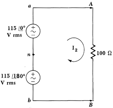
    While you are certainly free to use that convention, you must keep in mind the ramifications of misusing it, which you have in fact done. You have changed the polarity of the voltage source without acknowledging the double-negative sign that your measurements impose. The result is the circuit shown below.

    If you solve this circuit for I2 you will discover that I2 opposes the voltage of the lower power supply, which by electrical definition makes the lower power "supply" actually a "load" which is consuming power instead of supplying power.

    You can't have it both ways. Either the two power supplies are in-phase or out-of-phase. If they are out of phase, then one of them needs to be a load instead of a supply.

    The bottom line is that you are misapplying your relative point of reference as being an absolute point of reference, and redefining the circuit based on this relative reference point. Doing so will result in erroneous circuit analysis, that without the application of some voodoo mathematics to correct the missing minus sign, will result in one power supply being a load.

    If you acknowledge the missing minus sign, then the two sources are in-phase. If you don't acknowledge the missing minus sign, then one of them must be a load. That's the dilemma you face if you choose to make your reference point oppose the natural polarity of a system.

  2. #32
    Join Date
    Jun 2007
    Location
    Wichita, Kansas
    Posts
    1,795
    Quote Originally Posted by Rick Christopherson View Post

    If you solve this circuit for I2 you will discover that I2 opposes the voltage of the lower power supply, which by electrical definition makes the lower power "supply" actually a "load" which is consuming power instead of supplying power.
    I would agree the I2 opposed the voltage of the lower power supply if and only if the power supplies were connected + to + or - to - and the lower supply had a lower voltage that the upper supply.

    Solving that circuit for I2 is simple. The voltage difference between A and B across the 100 ohm load is 230 volts RMS. The current I2 is simply 230/100 = 2.3 amps RMS. The current flows from top to bottom during the first half of the cycle when the topmost terminal is + and the bottom most is - and from bottom to top during the second half of the cycle.

    If you replace those two power supply symbols with batteries, what would you say about them then. For two supplies in series with a load, the positive terminal of one of the supplies must be connected to the negative terminal of the other supply just like you've shown.

    As shown, by convention, current flows from the positive terminal on the upper supply through the load to the negative terminal on the lower supply and from the positive of the lower to the negative of the upper. Assuming the supplies have the same voltage, that's the only way you are going to get any current through the load with the supplies connected in series as shown.

    The only other way to connect them in that circuit is negative to negative or positive to positive. In the diagram, connecting + to + or - to -, and assuming the two batteries/power supplies are exactly matched, the load would see no current at all. If the two supplies weren't exactly matched, one having a higher voltage than the other, then you would indeed see the lower voltage supply acting as a load on the higher voltage supply. Under those conditions, the 100 ohm load would see a current given by the difference in the voltage of the two supplies divided by 100.
    Tom Veatch
    Wichita, KS
    USA

  3. #33
    Quote Originally Posted by Glenn Roberts View Post
    Mike, I am just loving this thread. Here in Australia we use 50hz 240/415V. Where houses are generally wired in single phase, eg: one phase and neutral ( MEN Earthing). As you go down the street alternating houses use a different phase to balance the load etc.
    Some houses (where their maximum demand dictates or large loads, ducted air con etc) are wired for either 2 phases or 3 phases.

    For all too long I have been totally confused at your system when I see your equipment rated at either 110 or 220 etc. ( motors etc)

    NOW I KNOW. THANKS!!!

    How do you guys run large motors etc in a domestic situation? the current must be enormous.

    Here we generally only run up to 3hp motors on single phase and then go 3 phase. Hence the potential problem for people wanting to run large dust extraction etc if they only have single phase ( 240v)
    You're really fortunate to be able to get three phase in a residential environment - I wish we could do so here in the US.

    Load balancing across phases is done here in a more gross basis. In many cases, a whole neighborhood is supplied by one phase - that is, only one phase is brought into the neighborhood at high voltage. Then step down transformers are used to bring the voltage down to 240V center tapped, and each transformer supplies a few homes.

    Of course, really big motors are not used in a residential environment. About the biggest I can think of might be a 5HP motor on a table saw, and yes, they do take a fair amount of current at 240V.

    But there's a good reason why the US system is designed the way it is, and that reason is safety. In a residential setting, the highest voltage to ground is 120V. The only way you can receive a 240V shock is to put yourself across both wires of a 240V outlet. And while a 120V shock is dangerous, it's not nearly as bad as a 240V shock.

    I haven't traveled in Australia, but in England they have (maybe "had" since I haven't been there in a while) some "unusual" code restrictions because of the 240V to ground system. For example, the switches for lights in a bathroom had to be outside the bathroom (I suppose so that you wouldn't be standing in water when you turn the light on or off).

    Sidebar: I can imagine how that worked with kids, when one would turn the lights off while the other was taking a bath.

    There are multiple ways to do power distribution and each has it's advantages and disadvantages.

    One more sidenote: here in the US, people sometime ask for three phase in a residential setting. Most of the time the answer is simply "It's not available." But you can see the problem. Three phase is often not brought into residential areas. To supply it the power company would have to run additional wires, and of course, three transformers (or a special three phase transformer) would be needed to bring it into the premises.

    Mike
    Go into the world and do well. But more importantly, go into the world and do good.

  4. #34
    Join Date
    Dec 2003
    Location
    SF Bay Area, CA
    Posts
    15,332
    Quote Originally Posted by Rick Christopherson View Post
    While you are certainly free to use that convention, you must keep in mind the ramifications of misusing it, which you have in fact done. You have changed the polarity of the voltage source without acknowledging the double-negative sign that your measurements impose. The result is the circuit shown below.

    If you solve this circuit for I2 you will discover that I2 opposes the voltage of the lower power supply, which by electrical definition makes the lower power "supply" actually a "load" which is consuming power instead of supplying power.
    Well, if you take the voltage supplies out of phasor notation, you have simply 115 Vrms for the top voltage and -115 Vrms for the bottom voltage. The way you have them connected (+ to -) means they add and you get 0 volts and therefore no current flow, I2=0...as Rollie pointed out.
    Wood: a fickle medium....

    Did you know SMC is user supported? Please help.

  5. #35
    Join Date
    Dec 2008
    Location
    NSW Australia
    Posts
    38
    Mike thanks for the description. It makes sense now. As a general rule, in most residential areas ( and our HV network) the 3 phases are run. So 3 phase is common place. At one stage in our local area all new houses where wired ( up to the box) in 3 phase ( in case it was needed in the future)

    Yes 240v is potentially(pardon the pun) more dangerous and it has caused our large single phase motors to be of very limited availability and high cost. 3 phase motors (by comparison) are 'dime a dozen'. And they run slower than yours.(50hz etc)
    That said not every one has 3 phase at their home even though it is in all streets.
    Earth leakage CB's (RCD) are now wired on power and lighting circuits to help with the danger of 240v.

  6. Quote Originally Posted by Chris Padilla View Post
    Well, if you take the voltage supplies out of phasor notation, you have simply 115 Vrms for the top voltage and -115 Vrms for the bottom voltage. The way you have them connected (+ to -) means they add and you get 0 volts and therefore no current flow, I2=0...as Rollie pointed out.
    It was actually a rhetorical question, not one I was expecting anyone to solve. I also had a more complex version of this same circuit which included neutral currents and loads, but since this isn't an electrical forum, I wanted to keep it very simple.

    In any event, you should see why confusing a relative reference with an absolute reference creates problems. It is OK to "think" of the voltages as being above and below neutral, just so long as you do not make the mistake of "defining" the system that way.

Posting Permissions

  • You may not post new threads
  • You may not post replies
  • You may not post attachments
  • You may not edit your posts
  •