Page 5 of 29 FirstFirst 12345678915 ... LastLast
Results 61 to 75 of 428

Thread: Making plans to build a concrete bowl lathe - opinions welcome.

  1. #61
    Join Date
    Feb 2009
    Location
    Gods country: Mariposa CA
    Posts
    839

    Some more progress

    In the way of a full scale mock up on the particle board I will be using as one of the outside forms..

    It looks like the pulley set up will work just fine and I will have a dual spindle machine. The lower spindle will yield a 13" swing over the ways and use a tail stock where the upper will have a 48" swing over the ways.

    I have a slick set up figgured out for the motor mounting and belt tensioning. I just hope it works like I plan.

    Today I brought home a dozen 80# bags of high strength concrete and the heavy wall square pipe I will be using for the ways. I have some welding to do on em.

    I havent decided if the ways will bolt to the headstock colum or be cast into the concrete but I wont be mixing the concrete for about two weeks till I have the rest of the bits in hand so no hurry on that decision..

    I'll let the pictures tell the rest of todays story.


    Almost 1000# of concrete


    I have two options for the horizontal body of the machine under the ways and havent decided. Both are 8" pieces of water main pipe, one is ductile iron and the other is c-900 pvc... The iron would hold paint real well but the pvc could remain un-painted and is nice and smooth.


    More to come

  2. #62
    Join Date
    Feb 2008
    Location
    torrance, Ca
    Posts
    2,072
    this project is really starting to materialize. It's nice to see all the pictures, keep them coming. Love to see it all.

  3. #63
    Join Date
    Oct 2008
    Location
    Eau claire, Wisconsin
    Posts
    3,084

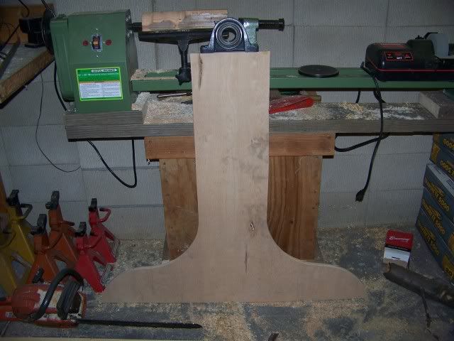
    Soon the day will come for the beast to live!!

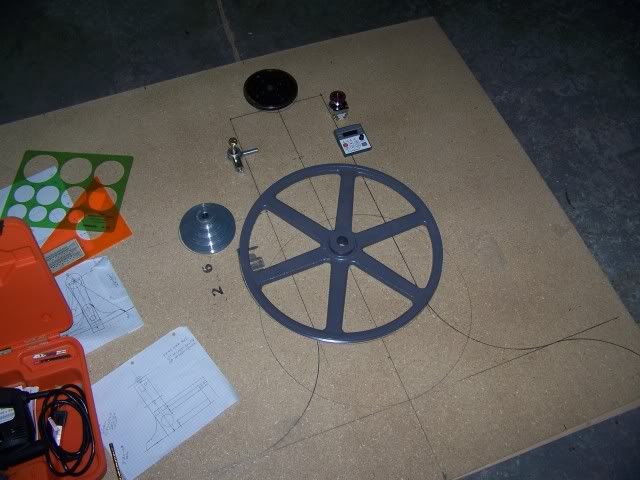
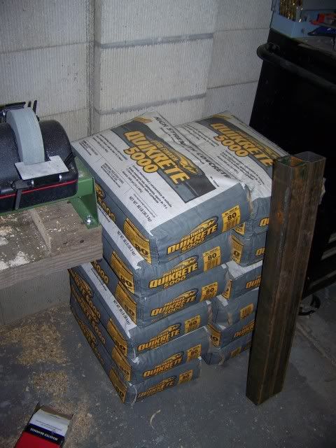
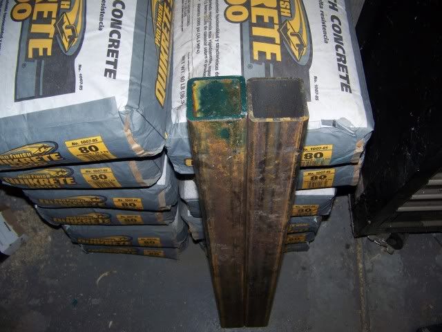
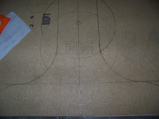
    Mark, Do you feel sort of like Dr. Frankenstien building the monster from pieces and parts gathered here and there? Soon the monster will live!!!! Great work so far and you have put lots of thought and effort into making a quality turning machine. We all can't wait to see the beast spinning and curls flying through the air!

    Have a great day!

    Jeff
    To turn or not to turn that is the question: ........Of course the answer is...........TURN ,TURN,TURN!!!!
    Anyone "Fool" can know, The important thing is to Understand................Albert Einstein
    To follow blindly, is to never become a leader............................................ .....Unknown

  4. #64
    Looks like a fun project. I'm wondering about the logic behind using a movable bed. As much effort as you're going through to keep the spindle from vibrating, it seems you'd want the bed and tool rest to be on something more substantial than some steel hanging on Unistrut. In addition to vibration problems, I'd think there would be other issue with leveling and having the two rails coplanar. I think I'd imbed the rails in as much concrete as possible, and make or purchase as stout of banjo as possible.

    Looking forward to seeing it all come together, however you end up doing it.

  5. #65
    Join Date
    Mar 2007
    Location
    Jackson, TN
    Posts
    202
    I'm not much of a turner (may become one someday), but I've enjoyed this thread. My dad made his lathe out of plans in a woodworking mag some 20 or 25 years ago, and he still turns on it weekly. So, I have an affection for homemade lathes.

    Some of you may have seen this in another post, but I stumbled across another interesting homemade bowl lathe on Craigslist. Check out the spindle size on this sucker...wow!

    http://atlanta.craigslist.org/tls/1095799846.html
    Where will you be when you get where you're going? -- Jerry Clower

  6. #66

    Something to think about

    Mark,

    Looking at your large dia. pulley got me to thinking. On a larger machine to transfer the torque from a 2 H.P. motor to the spindle shaft in the 50 to 500 R.P.M. range they use two (2) belts totaling 1 1/2" in width and it takes all of that to not have belt slip.
    I just wanted you to know that so you don't build undersize.
    Happy thinking.

    Dave

  7. #67
    Join Date
    Feb 2009
    Location
    Gods country: Mariposa CA
    Posts
    839
    Quote Originally Posted by Jeff Nicol View Post
    Mark, Do you feel sort of like Dr. Frankenstien ...


    Jeff

    Yeah, kinda jeff. I have been confused with a mad scientist,,,


    I made some progress on the critical end form and got some pics of the progress cuz I know I like pics as much as you all do

    All yer comments are welcome and duly noted ...

    After I cut out the shape in the partical board I laminated it with 1/4 luan veneer for a smooth finish...


    My daughter decided more ballast was in order..


    Glue and screws!!

  8. #68
    Join Date
    Aug 2005
    Location
    Midwest
    Posts
    2,043
    Dave O,
    I've kind of read the same thing about belts. Then I remembered that cars used to use std V-belts for years to power things like AC compressors (that can present a 10hp+ load). These systems worked fine for many years without slippage unless the belt was worn. I suspect that the the ribbed flat belts run smoother and are more efficient but are not necessary for a build like this. Two belts would be total overkill IMHO.

  9. #69
    Just some observations

    I thought you wanted mass, now it seems like it is very narrow
    and the pulley is wider than the base so you will have to incorparate some type of guard, why not make the width taper from the top to the bottom. This would provide more strength and mass and make the bottom pulley look more like a part of the design instead of an after thought

    just my 2 cents

  10. #70
    Join Date
    Feb 2009
    Location
    Gods country: Mariposa CA
    Posts
    839
    Yeah Phil, The big pulley was an after thought... It will be easily removable and I'm thinking I would likely do without it 95% of the time.

    I am going for mass way down low to keep the center of gravity as low as possible. Looking at it from an end view it does look rather narrow now that its cut out to scale. Lets see what it looks like when its all said and done. I think it's gonna look sexy

    I agree with you on the belts Dick, one is sufficient. At work I have a lot of belt driven machines (hvac) some have multiple belts on them but only on the 10hp and up motors.

  11. #71
    Join Date
    Feb 2009
    Location
    Gods country: Mariposa CA
    Posts
    839
    Quote Originally Posted by Don Eddard View Post
    Looks like a fun project. I'm wondering about the logic behind using a movable bed. As much effort as you're going through to keep the spindle from vibrating, it seems you'd want the bed and tool rest to be on something more substantial than some steel hanging on Unistrut. In addition to vibration problems, I'd think there would be other issue with leveling and having the two rails coplanar. I think I'd imbed the rails in as much concrete as possible, and make or purchase as stout of banjo as possible.

    Looking forward to seeing it all come together, however you end up doing it.
    The design no longer includes uni-strut Don, the first sketch was purely conceptual. I don't want to cast them into the concrete, so the two steel ways will be welded to end plates that will be held in place with some BIG bolts. That will give me the flexibilty for fine tuning them to attain level.

  12. #72
    Join Date
    Nov 2008
    Location
    College Station, Texas
    Posts
    200

    My homebuilt lathe

    Mark,
    I really like your idea about a concrete lathe base. I built a wood lathe base and am pretty pleased with it. I wanted to build the most out of wood instead of metal, since I'm a woodworker. The three main metal parts are the headstock spindle, tailstock spindle and bed. See the attached picture.

    I did learn several things the hard way. First, the alignment of the headstock parallel to the bed both vertically and horizontally is critical. Second, alignment of the tailstock to the headstock is just as critical. Without these, spindle turning or even using the tailstock to support a bown in the initial stages of turning will be a problem, and drilling using the tailstock almost impossible. I used a 16" long 2" dia round bar turned down to a 1 1/2" dia headstock spindle with 1 1/4X8 threads. It is supported by two deep groove bal bearings in spherical mounts, which I think is the critical part. This allows you to align the spindle regardless of how mis-aligned the vertical bearing supports are (within reason). Do you plan to have a hole down the center of the headstock spindle for a knockout bar or vacuum chucking? I found machinists not very interested in drilling this long of a hole.

    There are a lot of other lessons learned that would be too long for this thread. If you are interested, please send me an e-mail through the forum and I'll be glad to share.

    Good luck. It's not just the destination, but also the journey...
    Attached Images Attached Images

  13. #73
    Join Date
    Feb 2009
    Location
    Gods country: Mariposa CA
    Posts
    839

    Nice looking lathe Dave

    I'm suitably impressed. The alignment of the headstock spindle is not as critical for turning bowls. I figgure I can adjust mine by adding shims under the pillow block bearings if need be. Also the ways will have some adjustment to em.

    Made a lil progress with the forms yesterday but I need a few more parts to proceed further.


    Both end forms screwed together book matched so they will be identical.


    Spent some quality time with the belt sander,,lol lol


    More to come...

  14. #74
    Join Date
    Dec 2008
    Location
    Parker, CO
    Posts
    25
    Awsome thread. Great to see this thing evolving. I'm thinking of casting a riser block for a Powermatic Model 90.

    I see you chose a TECO N3 for the VFD. Why this one over the Teco JNEV-203, which is also sensorless vector constant torque in a protected chasis? I assume that $100 is worth something but what?

    Thanks,
    Mike

  15. #75
    Join Date
    Feb 2009
    Location
    Gods country: Mariposa CA
    Posts
    839
    Quote Originally Posted by Mike Zipparo View Post
    Awsome thread. Great to see this thing evolving. I'm thinking of casting a riser block for a Powermatic Model 90.

    I see you chose a TECO N3 for the VFD. Why this one over the Teco JNEV-203, which is also sensorless vector constant torque in a protected chasis? I assume that $100 is worth something but what?

    Thanks,
    Mike
    Thanks Mike,
    I'd like to see the riser block when you get it done. Concrete is a great building material.
    I wanted the remote mount control panel the N-3 offers. That way I can mount the VFD on the wall of the shop out of harms way and still have the controls at the ready.

    I would have made more progress this weekend but I'm waiting for a few parts before I proceed.

Posting Permissions

  • You may not post new threads
  • You may not post replies
  • You may not post attachments
  • You may not edit your posts
  •