Results 1 to 7 of 7

Thread: Made 6" inlet for Unisaw

  1. #1
    Join Date
    Aug 2008
    Location
    West Melbourne, FL
    Posts
    84

    Made 6" inlet for Unisaw

    I'm currently installing a 6" PVC system in the shop and wanted to upgrade my tool's ports form 4" to 6". The first one I tried was on my Unisaw. To create the inlet, I used the method of creating a template for the desired shape, rolling it on the sheet metal, and tracing it's outline. What I found difficult was getting the flanges on each end correct. The flange tabs weren't even and it wasn't going to be a good seal. I came up with a method that doesn't require as much accuracy or skill with forming metal.

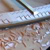
    I still used the template, but I didn't add any tabs for the flanges. The only addition to the profile is a 1" of overlap at the seam. The template jig is in the upper-left corner of the picture. For the pipe side, I cut the end off of a PVC cap. Also in the picture is the remainder of the cap. It will be used later. For the saw side, I make a template of my desired shape. Also in the picture is a flange with the same shape cut out.

    DSC04082.jpg

    Next, I formed the metal and attached one end to the plywood flange that attaches to the saw. I used screws to attach the metal to the top and sides. I left the bottom (where the overlap is) loose for now.

    DSC04083.jpg

    I installed the remainder of the PVC cap in the other end and secured it with a hose clamp. The ID of the cap is tapered, so it must be installed correctly. This taper also provides a quick disconnect to the mating pipe.

    When the hose clamp is tightened, the metal will conform. At the plywood flange side, the bottom of the metal will adjust and can now be screwed into the plywood. The plywood is 3/4" so it has room for error. Last, rivet the seam and seal the pipe to the plywood.

    DSC04088.jpg

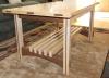
    Here's the installed inlet.

    DSC04089.jpg

    continued on next post ...

  2. #2
    Join Date
    Aug 2008
    Location
    West Melbourne, FL
    Posts
    84
    Here's the final install. Notice how the PVC has moved from the previoius photo. By loosening the hose clamp, I can position the outlet to line up with my outfeed table. That is another nice part of this method. It has a little adjustment. The main benefit is that the sheet metal work doesn't have to be done well. With the 3/4" overlap at the plywood flange and the 2" overlap on the PVC, there's plenty of room for error.

    DSC04090.jpg

    Here's the before and after cutouts on the cabinet.

    DSC04085.jpg

    DSC04086.jpg

    After the table saw, I made an inlet for my 8" jointer. It came out much better. One major improvement was that I increased the area of the cutout in the plywood flange. Static pressure increase at the hood is much better if the air is gathered through a nozzle of decreasing area. On the Unisaw, I should have made my plywood flange taller with a larger opening.

    DSC04091.jpg
    Last edited by chet jamio; 12-31-2008 at 1:20 AM.

  3. #3
    Join Date
    Aug 2005
    Location
    Glenmoore, PA
    Posts
    2,194
    Chet, looks very nice. I did something very similar with mine. I took a square piece of MDF and routed a circle all the way through it the size of the OD of the pipe. I cut off a 10" section of the pipe and secured it into the MF, caulked it and I had essentially a flange. I cut the cabinet to match the 6" pipe and attached the MDF. From there I just used a coupler to attach the the rest of the run. I don't have flex hose though.

    One thing that I did that made a MAJOR improvement in the dust extraction on the saw was to seal the bottom. The "trey" that diverts the dust down to the port has a lot of space between it's edges and the cabinet and that allows dust to collect under it. I sealed that with HVAC tape and it completely cured the problem.

    While you can't see what I am talking about in any of these pics, you can see pretty much the rest of my DC setup.

    http://www.sawmillcreek.org/showthread.php?t=80262
    Last edited by Larry Fox; 12-31-2008 at 8:15 AM.

  4. #4
    Join Date
    Sep 2008
    Location
    Chesapeake, VA
    Posts
    242
    Thanks for the post! I've been considering how best to make one for my G0490, now I have a reference pic.
    There are 10 types of people in the world, those who understand binary and those who don't.

  5. #5
    Thanks for the post. Nice work. Your photos and explanations will help me in my upcoming DC project.
    Duane McGuire

  6. #6
    Join Date
    Aug 2006
    Location
    Flagstaff Arizona
    Posts
    204
    Those came out great! I went the lazy route and used a register boot on my G0490, but yours looks a whole lot nicer. The boots seems to work fine though, and the flex hose just fits on the end.

  7. #7
    Join Date
    Dec 2004
    Location
    NW Indiana
    Posts
    1,050
    Chet, since your using PVC for your dust collection. You might what to check this out.http://harderwoods.com/pipe.html
    If I saw this early when I was doing my shop. Would have done it in PVC.
    Nice job on your fittings.

Similar Threads

  1. Where are your tools made?
    By Lean Angle in forum General Woodworking and Power Tools
    Replies: 63
    Last Post: 08-29-2007, 6:55 AM
  2. Shop Made Joiner and Boatwright Tools Part One
    By Bob Smalser in forum Neanderthal Haven
    Replies: 3
    Last Post: 12-10-2003, 11:19 PM
  3. Shop Made Joiner and Boatwright Tools Part One
    By Bob Smalser in forum General Woodworking and Power Tools
    Replies: 2
    Last Post: 12-09-2003, 10:02 AM
  4. Shop Made Joiner and Boatwright Tools Part Two
    By Bob Smalser in forum Neanderthal Haven
    Replies: 0
    Last Post: 12-09-2003, 2:26 AM
  5. Shop Made Joiner and Boatwright Tools Part Two
    By Bob Smalser in forum General Woodworking and Power Tools
    Replies: 0
    Last Post: 12-09-2003, 1:13 AM

Posting Permissions

  • You may not post new threads
  • You may not post replies
  • You may not post attachments
  • You may not edit your posts
  •